| The
Carriage
The
carriage was worked on parallel to other steps. This is not the usual
way,
but I got used to completeing as much sections as possible up to the
next
painting step. This way I collect the sections to paint them at once
and
then go ahead. This saves worktime, by not getting the airbrush ready
all
the time.
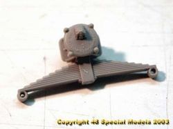
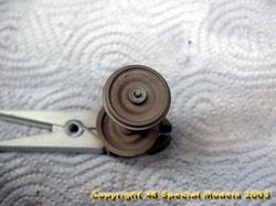
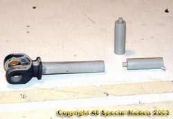
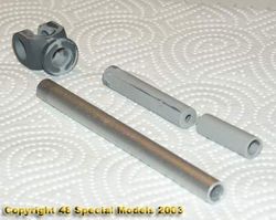
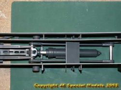
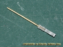
When
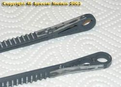
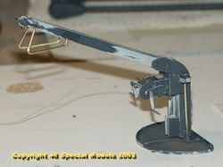
assembleing the carriage I started making the hydralic cylinders first.
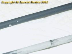
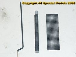
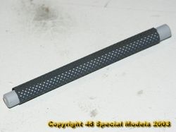
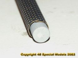
The
mainstrut which controls the main cylinder is made from two parts (M7)
which doesn't make any sense at all. Before getting lost in sanding and
leveling out, I simply cut of the whole thing and replaced it by a 8mm
aluminum tubeing. It was sanded at the cementing areas and glued in
place
with superglue. After that it was cut to lenght. The strut is straight
now and runs smooth to the cylinder.
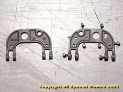
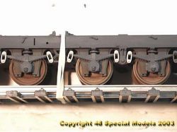
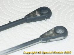
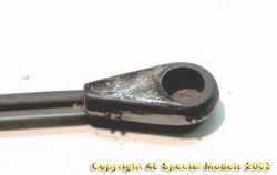
The
support struts C29 have holes on the inner sides, which result from
production.
These holes will almost not to be seen, but are a weakness in
structure.
I filled them with superglue and glas bubbles and sanded them down to
size.
So they vanished completely. The support struts also could be exchanged
with brass, but that I skipped for myself.
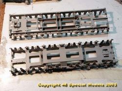
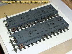
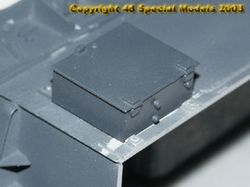
It
is helpful to preassemble all sections of the carriage. This means also
the supporting bulkheads inside the carriage. Again all the many
depression
holes need to be filled first! This is nuisance and time consuming. I
built
the bulkhead boxes beforehand and painted them.
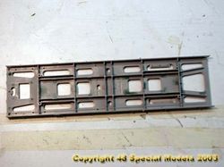
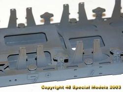
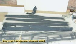
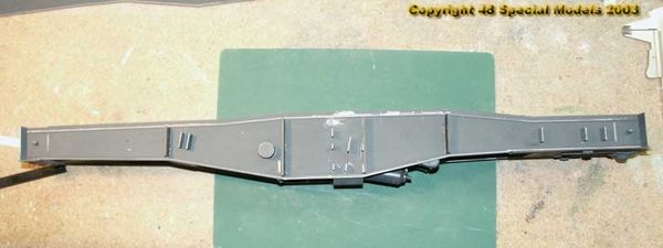
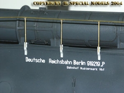
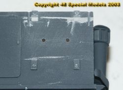
The
four sidewalls of the carriage do have each three depression holes on
the
outside! They also have to be treated with superglue. It is helpful to
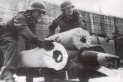
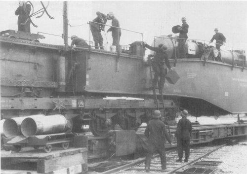
check the surface by useing original photographs. There are a lot
of pictures of the Leopold in the internet. Some can be reached from
our
linkpage too.
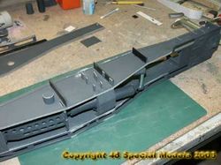
The
sidewalls have been primed grey first and then painted with XF-64 tank
grey. The assembly of the whole carriage is quite complex, because a
lot
of sections need to be integrated. It is importend to take care of all
moveable parts, to keep them movable. Modellers who use the machined
barrel
by Schatton/48 Special Models should read the section
The
machined Barrel first!
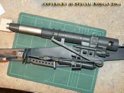
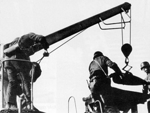
The
barrel will be testfitted first and adjusted so that it can be cemented
in place later simply. When useing the machined barrel additional
ballast
is needed in the lock and carriage!
When
the barrel mechanism works fine, it will be cemented to the inner
sidewall,
on one side only first. The whole section will be slipped to the slots,
adjusted and cemented with thin superglue from the opposite side (in
between
the walls). It is helpful to testfit the whole carriage beforehand
first.
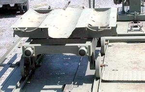
The sides of the carriage consist of a double wall construction, which
has bulkhead walls for strength. For a to me unknown reason, Trumpeter
missed to design a minimum amount of stuctural support here. I can't
imagine
that the carriage can be build without additional supporting bulkheads
at all. It definitly needs them, if the machined barrel is used!
Conditional on the weight of the barrel the occuring forces at the
cradle
need to be transfered most even to the carriage, to prevent it from
going
out of shape.
I
started preparing all parts. The lift mechanism needs a scratch build
construction,
when the barrel will be movable or fixed in raised position. I decided
to make the barrel movable and I am curious if it will work.
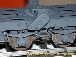
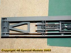
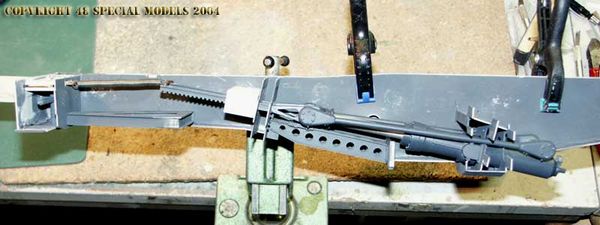
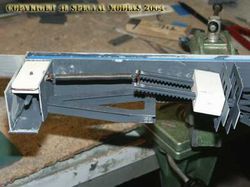
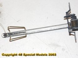
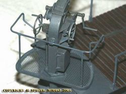
The
original lift mechanism works as follows:
The
toothbars are moved by a gear and an electric engine and determine the
elevation of the barrel. The lower hydraulic cylinder connected to them
equals the barrel weight by hydralic pressure. This way the barrel can
be moved with a minimum of force. The parallel support struts transfere
the forces to the barrel. To solve this without loss of force the
mechanism
is guided on a rail in the middle. This secures a direct transfering of
forces. Underneath the barrel itself only a recoil break cylinder is
mounted,
which stops the barrel recoil.
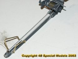
On
the model the principle works the same way, except for the mass
compensation
by the main hydralic cylinder. This one is without function, but
moveable.
To double his task another source of force is needed, i.e. a coil
spring.
The missing engine support is compensated by the scratch build guidance
block, which takes care of parallel toothbar movement. To the end of
the
toothbars a coil spring is fixed, which is also fixed to the inside
carriage
end. Therefore the carriage wall needs structural support.
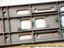
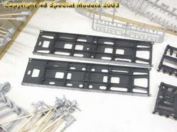
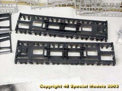
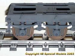
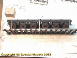
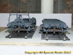
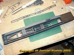
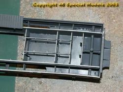
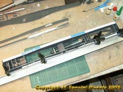
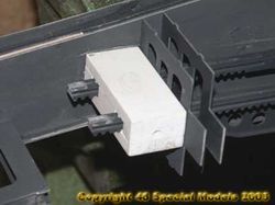
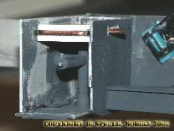
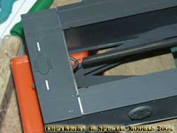
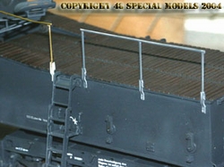
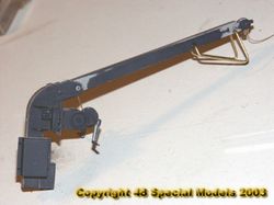
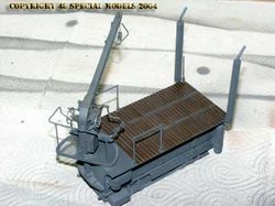
The
whole carriage box needs to be supported by additional bulkheads
inbetween
the outer and inner wall. Unfortunatly no data on the original where
available
on that item. So I had to improvise. In general it can be assumed that
the vertical bulkheads at positioned at areas, where the dimensions
change
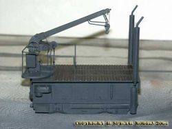
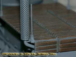
and cross bars are located at the lower side. So I put in 2mm thick and
12mm wide styrene sheets here. These were cemented inbetween the edges
on the inner side of the sidewalls. The way the horizontal bulkheads
were
placed can be seen good on the pictures. So they don't show after
assembly
they are cemented about 1cm above the lower edge. This makes it a kind
of a boxlike structure. On the top I cemented a strip of 1mm thick
styrene
along the whole edge. This is necessary, because the second,
outer
sidewall can be finaly cemented in place only after the barrel
mechanism
is mounted. At the right, smooth side this already can happen when the
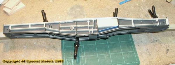
bulkheads are installed. To prevent the carriage box from bending, it
should
be clamped to a even support, like an aluminum angle profil. This keeps
it straight. Now it can be superglued. The left sidewall will be only
put
in place dry, to adjust the construction. It can be cemented in place
after
the barrel mechanism is installed completely!
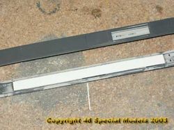
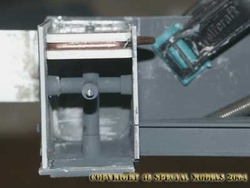
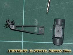
Now
the changes on the lifting mechanism are made. Therefore two 5mm
styrene
sheet of 2x4,5cm are cut out and sanded parallel. They have to fit
smooth
inbetween the inner walls. On one sheet the centre axsis is marked and
the exact distance of the guidence notches of the toothbars too. There
will be two 1mm wide and 1,5-2mm deep slots cut out, in which a strip
of
1mm styrene is cemented. It shouldn't be a much harder material, to
prevent
wear. These will be sanded down to 1mm of hight. This can be
managed
easy by placeing inbetween a strip of 1mm thick styrene. Now only
sanding
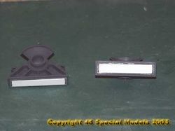
to fit and the parallel guidance is ready. Now a distance block of
4,5mm
needs to be placed inbetween the two plates. A centered hole on 3mm is
drilled centered to the left and right side, to take a bolt from
aluminum
or brass wire. These guarantee a stable rest and the posiblity to
adjust
the angle, before cementing in. The guidance block is positioned direct
in front of the second bulkhead and adjusted to its angle. To the inner
sidewalls fitting 3mm holes are to be drilled too.
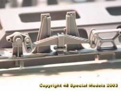
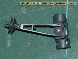
Is
it placed correctly the toothbars will walk through it smooth, prallel
and straight in line with the hydralic cylinder. Also the toothbars
don't
leave the block and point out about 5-8mm. To both of the tips a 2mm
hole
is drilled and a fitting, strong wire is cemented in. It makes the rest
for the coil spring. To center the spring the wire shouldn't be
straight,
but bend in the middle.
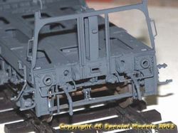
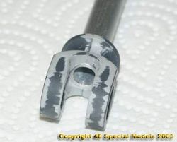
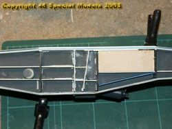
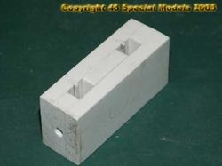
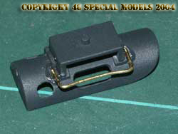
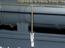
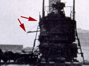
On
the opposit side a eye is mounted to the carriage inner wall. Therefore
to the opposite side of the wall (where the corss rests) a support
needs
to be mounted. Otherwise the 1,5mm thick wall will not last long to the
forces of the barrel weight.
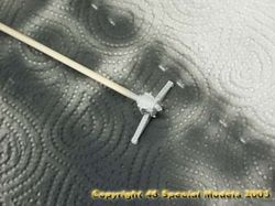
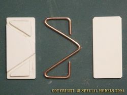
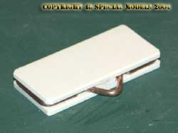
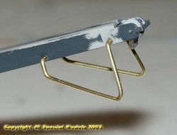
It
is recommended to bend an eye hold of 2mm welding wire (see
picture).
This will be placed inbetween two 2mm styrene sheets. As spacers some
sheet
angles are added inbetween them. They give contact to both sheets. The
whole construction is placed into the carriage end box. Therfore a slot
for the eye needs to be cut to the inner bulkhead. Simply drill two
holes
side by side and cut out the space between them. To find the right
position
use the lower edge of the coverplate. It tells the maximum hight. The
eye
plate should be positioned as high as possible, to use the spring force
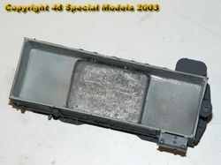
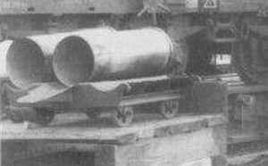
best way. Into the space below ballast is filled!
The
biggest problem now is to find a fitting coil spring. Fortunately I had
one in my spareparts box. It is good to keep everything!
Before
placeing the barrel in, the barrel angle is needed to be positioned on
the right side first. Below of the angle point a layer of supporting
sheets
is to be added. By adding several layers of styrene sheet the space
below
the barrel angle point is filled up to the support block inbetween the
doublewalls. The reason therefore is to transfer the forces from the
angle
to the sheet into the block and finaly to the carriage, by cementing
all
layers plain together. This prevents the parts getting out of shape by
wear.
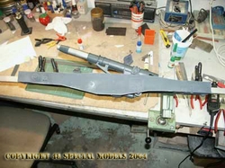
For
further assembly the parts should be again temporary mounted to a
aluminum
l-profile. Even better if this is fixed to a ball joint vice too. This
lets you turn the whole thing into position with only one move. Also
the
carriage is held straight and bending is prevented.
To
adjust the barrel straight the angles need to be parallel! Is the angle
positioned on the right, the whole gun can be put in place and checked
on mobility. The coil spring needs to be unhooked therefore! If
everything
does move right, the other side can be mounted on.
Put
in first the inner side wall, followed by the outer sidewall and the
upper
cover. After that cement the left angle in place. So it has to be
pushed
in from the side it is a little tricky to be cemented in place. Use a
thick
and slow superglue in this case. Styrene glue doesn't work here proper.
Before going ahead let the glue set long enough! Keep the barrel jacked
up eventually during that.
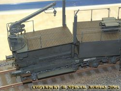
The
carriage is now finished almost. All the small parts need to be added
now.
Which will not be talked about in detail here.
Before
putting on the covers at the far ends of the carriage, the space inside
should be filled with ballast and secured with glue or resin. Now the
spring
can be hooked in and show if the mechanism works. My gun works proper.
The barrel keeps in any elevation without shakeing or sinking and can
also
be lowered completely. Nevertheless don't forget it is only plastic.
Don't
try to hard.
|