
Mistel 4 Me 262
A1/A2
in 1/18 scale
Author
Th. Schrecke 21.03.2007
All modell pictures copyright 48Special Models/Thorsten Schrecke
2007-2010
|
| Pre- Notice
This is an making of report from a personal point of view, which is by now completed.
All pictures and text shown here are owned and protected by copyrights of the author Thorsten
Schrecke/48Special Models and others. Any use, also in particular,
without written permission by the owner of the rights is prohibited.
This model was built by use of kits manufactured by Admiral
Toys, which had been available in our webshop earlied. The trolly is a own construction and not available as a kit!
|
Index
|
Pre-Work
Pre
work on this model is quite simple, due to the fact I already did it
for the 1/48 scale kit. Only the precise enlarging of the plans to meet
the right scale, was necessary, to prevent incorrect measures. By help
of modern computers it is no problem to scale the plans to the fitting
size and print it onto paper, but only in parts, due to the papersize.
Because of the papersize puzzeling starts after that, to bring together
the parts and fix them with tape permanent.
After quite a while you get an construction plan indeed in 1/18 scale.
First you notice the 4mm wide lines in the plan and the masureing
problems that will occure from them. Like always when enlarging from a
smaller original everithing gets bigger even the lines! This is why the
complete plan needs to be checked and measures need to be established
newly. The size and thickness of parts need to be calculated new and be
compared with the original.
After having finished this I realised that it would take me much longer
than I thought to make this model. There are no pre-produced parts at
all anything needs to be manufactured by hand! Also some minor
questions arrise like "what material do I make this from?" or "What
forces need this thing to take?'
The last question is answered easily, because the weight of the Me 262
model is printed on the box they come in and is 2.5kg each. No
lightweight aircraft indeed and not to be compared to any usual plastic
kit. Two of them make 5kg without modifications! Useing plastic sheets
won't get you fare here. This asks for a more realistic construction.
After thinking about the problem for a while I decided, for structural
reasons, to design the trolly body from plywood and the main axle from
aluminum. The main wheel mout was designed useing both materials. But
how about the wheels ?
Making rubber tires myself
was much too much work. Making wooden or Aluminum wheels also. I
thought about it and went to my favourite RC-model store around the
corner and looked for fitting aircraft wheels. There were some that had
the exact size I needed! This fact also proofed my scale calculations,
too!
Now all necessarities for the construction had been checked and I could start building the model.
|
The Me
262 model by Admiral Toys
The
Me 262 models by Admiral Toys are fine made replicas of the original.
You have to accept some minor changes, due to the fact the 1/18 scale
models have to meet some structural strength facts a regular palstic
kit never has to face. Also the fact they are designed as toys, that
have to meet special strenght parameters, needs to be remembered here.
All the bolt counters will shake heads about this, but nobody stops
them in making all the changes they think are needed. After that you
may not touch the model at all, because it will fall apart, but who
cares, except me?
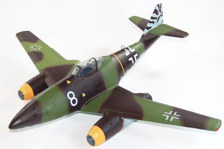
Copyright Admiral Toys 2006
|
The Me-262 A1 from Novotny as offert by Admiral Toys.
|
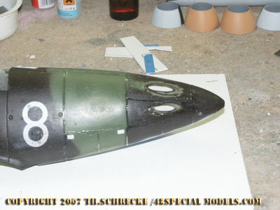
The paint of the original model is obsolete which needs no explaination. But it is still smart to protect the markings with tape from being sanded. They might be needed later eventually.
The guidance aircraft is keept mostly the way it comes from the box.
The necessary conversions on the bomb Me 262 are work enough. The
cockpit has to be erased, landingear also and the nose section needs to
be modified too. Also the radio equipment and all the wire antennas
will go.
This may generate some spare parts when done properly, which may be usefull later on. So take your time.
Me 262 destruction
All
who get wet eyes now may been told that the models used here are
slightly demaged at all and wouldn't be on sale therefore anyhow. Now
they serve a higher purpose!
To convert the Me 262 first the whole model needs to be taken apart
into its bits. That is not quite as simple as many may assume.
The
Admiral Toys model is glued and screwed too. So it may happen that
after all screws have been taken off nothing may happen. Now the right
touch is asked for to get parts apart. The pictures below show the
disassembled model and its inner structure. An important information
source for anybody how want to do the same, because it shows how
to make it. After disassembling it you get a large plastic kit.
The wings don't need to be modified at all, except for the landingear
which can be removed (at the bomb only). The landingear bays will be
bolted over with a fareing of "metal sheet", here a piece of plastic
card, which will be cut to fit an glued in place. As a template you may
use the landingear covers that have been removed before.
Inside
the fuselage many more things need to be converted and removed, which
makes a careful disassembling necessary. All screws are covered with
plastic caps and sometimes also secured with a drop of cement. There
are several ways to remove them.
Most simple is to drill a small hole to them and screw another screw
through it. This will lift the cap. At the fuselage the screws are
lowered deeper inside, so there will be no way for screwing and
lifting. Here the screw will be screwed into the cap and removes it by
pulling it outward or moving it from side to side. So the model needs
to be covered with putty at many placed later on at all, the caps can
be replaced or simply filled up with putty.
After disassembling
all parts, they need to be checked for sink holes and edges. This is the
chance to get rid of them. All glueing edges should be sanded and
remains of cement should be removed carefully.
|
|
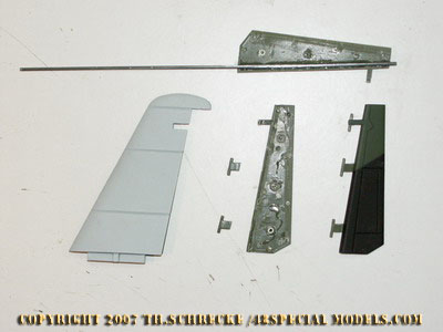
The wings need to be taken apart with care. Check for screws and cemented bolts carefully first!
|
First unscrew all screws you can reach.
|
|
|
The
landingear will be disassambled and taken out. First unscrew it
completly and then cut out a section from the landingear box to remove
the landingear safely.
|
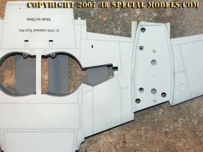
The engine gondolas are screwed to the wing from the inside!
First the gondola has to be disassembled and after that it can be
removed from the wing. Additionaly there is a plug in connection.
|
|
|
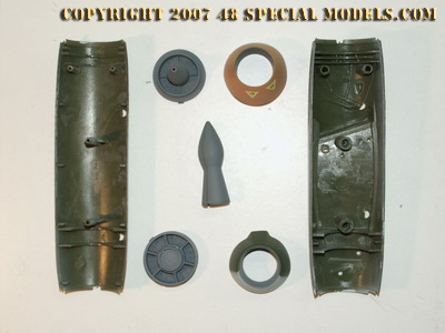
The
parts of the engine gondola. All parts should be cleaned after beeing
removed. The jet parts are only put in, not cemented, so they can be
removed without damage.
|
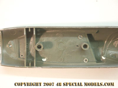
Inside
view of the engine compartment. When disassembling first remove the
endparts of the jet intake and exhaust. Then the lower half can be taken
off. This part is cemented very good so take care. Use careful dosed
force to loosen the part without breaking it.
|
|
|
Through
the three holes in the top section the gondola is screwed to the wing.
These screws can only be removed after the lower half is removed first!
|
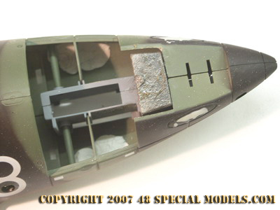
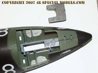
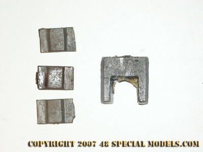
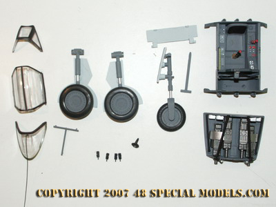
Very tricky installed is the balast weight in the nose section.
It is u-shaped and sits up on the front landingear compartment and tightens it
together. It also is glued in place with a contact rummer cement!
|
|
|
It can be removed quite easy with the help of a screwdriver.
Only after that the fuselage halfs can be seperated!
|
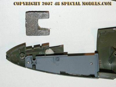
The
landingear compartment sides are screwed to the fuselage with two
little screws, too. These need to be removed too. After that the
landingear box can be sealed easier from the outside.
|
 |
|
The balast should be put back in place later on again.
|
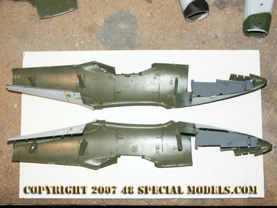
The taken apart fuselage parts. The tail part is hooked in only. That's helpful for later on work.
|
 |
|
The
left over parts that have been removed form the bomb aircraft. Keep
them. You never know when they are needed for replacements.
|
|
|
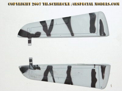
Conversion of the Me 262 into the bomb
The
Me 262 bomb has to be modified in some ways. It never had had any
cockpit or landingear and almost all not needed equipment was removed
from its fuselage. I am useing this opportunity to get rid of some
minor problems and mistakes, like the incorrect turnpoints of the
hinges of the stabilizer rudder and elevators.
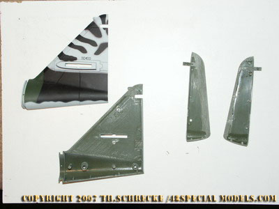
Conversion of the stabilizer and elevators
 |
 |
The
stabilizer is a seperate section of the fuselage (almost like the
original). Unfortunetely the hinge angles of the rudder are far off
from the original.
|
To correct this the parts were disassembled first.
|
|
|
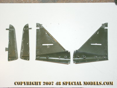
The stabilizer and rudder are to thick and needed to be sanded down until they fit perfect.
|
After that the lower hinge is removed. The upper hinge is kept because it is the rudder mass and needs to be in place!
|
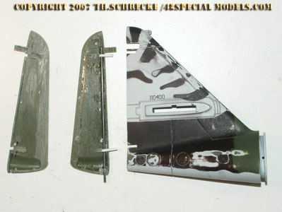
|
 |
From 2mm plastic sheet two new hinges are made and put on an 2mm steel wire axis.
|
The
not needed gap in the stabilizer is filled with 6mm PS sheet and
superglue. Where the new hinges are placed later on slots are cut with
a saw.
|
 |
|
After cementing the rudder fin halfs together again, the hinges at the stabilizer are fit in and cemented in place too.
|
A close up look at the new stabilizer hinge. Gaps are filled with thick superglue and sanded to fit.
|
|
|
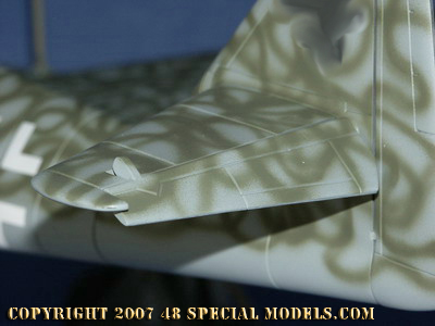
The completed new stabilizer. Clear to be seen the closer fit and new turn point.
|
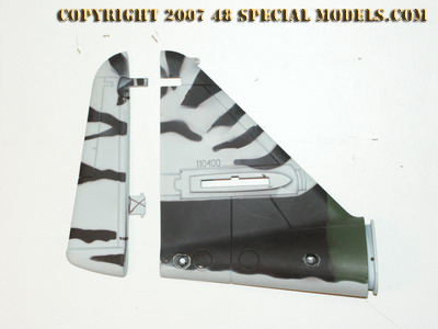
The new rudder angle meets the original now and is max. 15°-20° from the centerline.
|
|
|
The elevators also have wrong turn points, too. A simple change can solve this problem easy.
|
The corrected elevator on the final model.
|
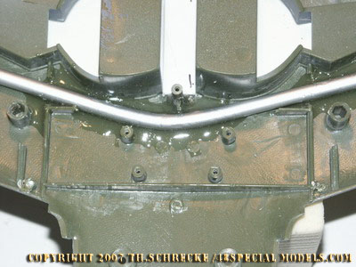
Conversion of the fuselage
The
Me 262 bomb was a dangerous weapon and a skill for engineers and
modellers as well. In our case things get easy by simply filling the
holes and gaps in the nose section with putty. This means
filling and egalising the weapons openings with putty to get a smooth
and even surface. Only the section gaps should be kept. The balast that
was removed should be put in again beforehand too, because the lack of
weight will let the model sit on its tail afterwards. The weapons bay
hatches are take off and the bulges on it are sanded even with the
surface. After that they are put back in and glued in place tightly.
Its helpful to glue a plastic sheet against the inside to strengthen
it, too.
The war heads that would have been placed on the Mistel 4 were varying.
One version would have consisted of liquid explosive, which asks for a
kind of tank. Another was planned as a construction of put together
explosives blocks that made up the nose section and was connected to
the fuselage. This explosives block should have been only covered with
paper and had had no metal sheet covers! The third version would
have been a mixture of both. This meant a block of explosives in the
nose section and a tank of liquid explosives placed inside the fuselage
(additional or instad of fueltanks) or reverse a tank of liquid explosives in the nose section and blocks of explosives place all over the fuselage.
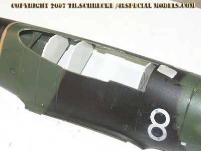
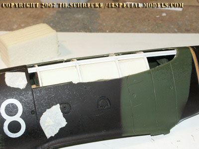
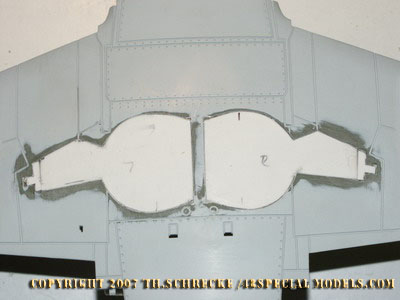
We
start taking off the canopy careful, because it can be reused. Also the
cockpit. The hunch behind the hood is cut off with a cutter or saw
carefully. Additional bulkheads made from 2mm palstic sheet are cut out
and put inside the fuselage. Use the cockpit front and back as a
pattern. These parts are glued to the struts where the cockpit was
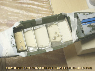
placed before. Inbetween the bulkheads some foam blocks are glued to
support them and fill up the space inbetween. Between the fuselage and
the foamblocks a 3mm gap should be left open. Here resin will be filled
in later to make the new fuselage hull.
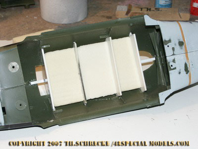
To
marke the centerline on the top a strip of styrene is cemented in. It
marks the new shape of the fuselage. By sanding down the foam the new
fuselage shape is made. To strenghten the new hull part a piece of
selfadhesive glassfibre tape (used for drywalls) is put on. At the
front and backend a cardboard bulkhead is glued in palce and sealed. It
will prevent the resin to flow through the whole fuselage, when filled in.
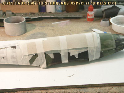
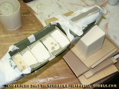
From the outside a layer of waxpaper following the fuselage shape is
applied and taped . This layer needs to be watertight sealed, so no
resin can flow out! For stabilising it a layer of thin cardboard is
applied too. The fuselage is now placed even on a rack and the resin
can be filled in slowly. It fills up the gap and makes a new hull.
The front landingear box is sealed with tape and cast with resin then, too.
Because the shape is round the material needs to come up higher. After
the resin has set, but hardened completely (can be recognized by when
it gets warm) the tape will be removed and the wax like material cut
roughly to shape with a cutter or knife. This saves a lot of time and
energy sanding lots of material down!
|
|
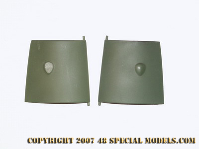
The weapons bay doors, first remove, then sand down the hunches.
|
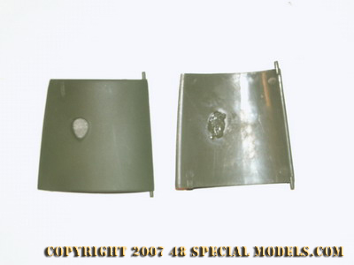
The hole on the inside is filled up with superglue, to prevent sanding trough.
|
 |
 |
The
weapons cover is "put in place" only. The guns holes are filled with
epoxy putty, the gaps with superglue. After that they are sanded even.
|
The
inside of the weapons cover. The light spots on the left have been
arresting pins that broke off because they were glued tight. They are
not important for placing the part in again, because it will be
cemented in place in complete!
|
 |
 |
With the help of a special plastic cutter the cockpit bulge is cut out along the graved line and taken off.
|
The ammo ejection gaps and the openingbulge are filled with epoxy putty and sanded to fit.
Sand the surface fist to make the putty stick better!
|
 |
 |
The
weapons bay covers will be cemented completely to the hull. Beforehand
the balast weights are put in place again and glued with 5min. epoxy
glue. Then the whole fuselage will be glued and screwed together again.
|
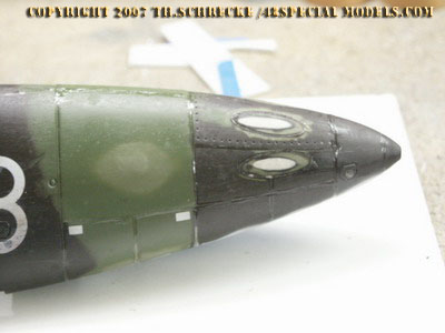
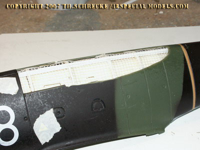
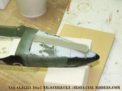
All engraved lines and gaps in the nose section are filled with superglue and sanded even then.
The nose (as well as the whole aircraft) didn't have any seams and gaps
at all! The warhead nose section was a formed explosives block
with a paper cover and therefore absolutely plain.
|
|
 |
Some additonal bulkheads are made and put in place. As a pattern the front and back end of the cockpit section is used.
|
Blocks cut from PUR foam are put inbetween the bulkheads then.
|
 |
 |
The fuselage shape is represented by a cemented in plastic strut. It supports the bulkheads and is a spacer to the foam blocks.
|
Before and after the cockpit area a cardboard bulkhead is placed.
|
|
|
On
top of the bulkheads construction a layer of self adhesive glass fibre
tape is sticked and cemented additional as well as tackered to the
foam. This layer will support the resin.
|
Then all is covered with a layer of waxpaper an cardboard. The better it fits the better it works!
|
|

|
In the space inbetween the resin is filled in. Fill up from one side only to let the air escape completely!
|
The front landingear box is filled with resin too. This makes shaping the bulged surface easier and faster.
|
|
|
Good to be seen here, the front cardboard bulkhead preventing resin from flowing into the fuselage.
|
The wax like consistence of half dried resin makes shaping it easy. Use a cutter to shape it roughly
|
 |
|
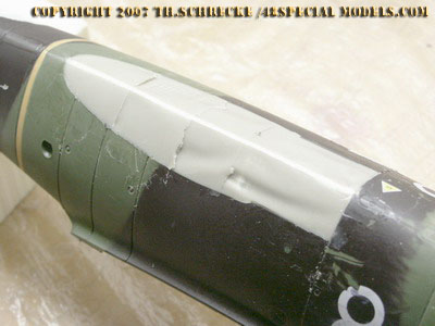
The
new fuselage section after taking the cover off. Not all areas have had
been sealed perfect. The missing material will be filled in with
polyester putty and sanded even then.
|
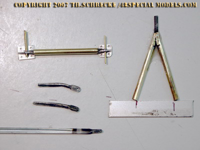
Making
the support struts was helped by a lucky coincidence, in shape of an old
umbrella. He supported me with the needed forkheads for the
struts. They were modyfied and glued into 4mm brass tubes.
|
|
|
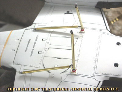
The main struts of the guidance aircraft are screwed into a 4mm bearing which was cemented into the wing
The connector plate was cut from plastic sheet and cemented to the wing too. The bolts are made from 1mm nails.
|
The front colapsing strut on the bomb.
For improvised connection 1mm nails were used, which can be taken off easy and fast.
|
|
|
The
main struts on the lower side of the bomb are more complicated to
measure out. The comecting principel is the same as on the guidance
aircraft.
|
The main struts on the lower side of the guidance aircraft.
The red balls are 6mm wooden perls, drilled wider and glued to the strut.
|
|
 |
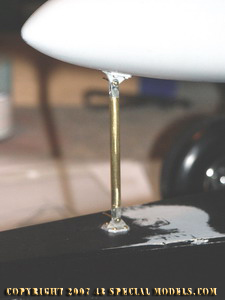
The
aft strut is cemented to the guidance aircraft. The right distance is
of importance her, so both planes stay parallel to each other!
|
First wedding of all parts. Although many details are still missing the models impressing look can be seen.
|
|
|
The
final aft strut was cemented to the guidance aircraft. Planned was a
3mm screw bearing which couldn't be realised due to time pressure. It
would have been better!
|
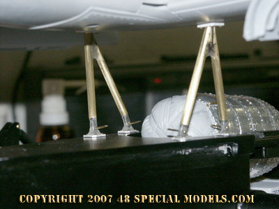
The
main strut between both aircraft. The struts need to be screwed to the
guidance aircraft first and then to be bolted to the bomb!
|
|
|
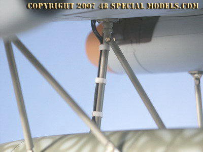
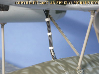
The wireing is taped to the strut and put in place loose.
|
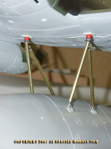
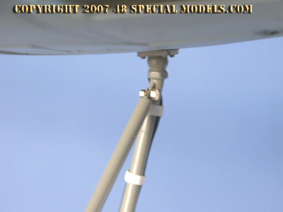
The upper main strut with balljoint. The diagonal strut was connected with a M1,2 screw.
|
|
|
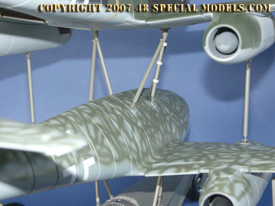
Backview. The colapsing struts on the wings are bolted on both ends.
|
Total view on the struts-"forrest". The frontside colapsing strut is also bolted on both ends.
|
|
|
The black wire is the parachute opening system.
|
Detail view of the lower main struts. The bolts are temporary and will be replaced with minature screws.
|
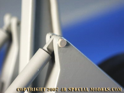
The support struts design
The
support struts on both aircraft are the most delicate part of the model
construction. The principel behind it is relativly simple but clever.
The lower aircraft is positioned to the trolley in three points. One
colapsing strut in the front an two main struts under the center wing.
Their exact position result from the center of gravity. The front
strut is positioned where the landingear was, because here is a forces
absorbing point of construction! It represents the front
landinggear some how. The main resting points result from the
construction of the Me 262. The wing has the middle beam which was only
used by Messerschmitt aircraft at that time. This beam is located in
the center of wight of the aircraft! Therefore it is the only fixing
point possible, which can carry the weight of both aircraft at all. The
connectors are known by size and making, because they were used on any
other Mistel aircraft. So they contained a explosive seperation bolt,
it can be assumed there where not many variations of it.
Therefore the main connecting point on both aircraft sits at the same
point. On the bombe the main struts to the guidance aircraft were
suported by a diagonal strut. Another diagonal strut between the left
and right main strut is not necessary, because they shape a tapez and
support themselfs this way. This way a sturdy connection over three
points is possible.
To save struts weight and make seperation of both aircraft as
aerodynamic and save as possible the guidance aircraft was connected to
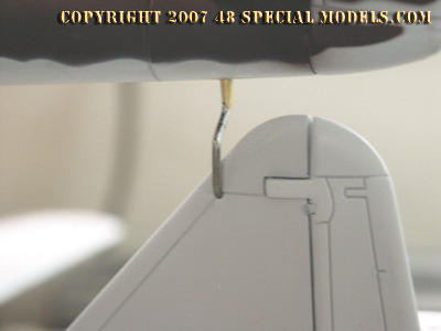
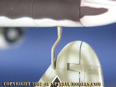
the bomb at the rear by a little colapsing strut with explosive bolt
only. On this special point there are no details know, as well as no
pictures available. All existing models use a prinzipel I invented. The
colapsing strut has the shape of a turned over questionmark. The
explosive bolt is located in the upper part. The lower part is placed
horizontal through the stabilizer of the bomb. The twisting point is
located at the highest possible place on the stabilizer which can take
any forces.
The wings need to be connected by
colapsing struts to prevent vibrations and to transport weight on a
larger surface. They have to take less forces and were fitted with
simple colapsing struts. The mounting point for them is the beam of the
main engine hold. The strut is errected vertical and connected with a
t-shaped plate to the lower engine compartment hull of the guidance
aircraft.
On the trolley are also colapsing struts
on each side. These are connected to the main axle and are put into an
opening in the lower wing. This opening is located on any Me 262 and is
used regularly for jacking up the aircraft when landingear maintanence
was made! Assumingly not even an explosive bolt was needed here for
separation. But a level adjusting would have been installed to
adjust the strut to the aircraft.
When making the
struts and especially the forkheads on them, an lucky incedent in the
shape of a broken umbrella helped me. I had had disassembled it, due to
enviorment friendly recycling and found the the struts of the umbrella
had have the right size and shape for the needed forkheads. Only the
U-shaped profile bothered me. The solution was as simple as clever.
Instead of making each forkhead at the laith for days, I took all
struts from the umbrella without damageing them. The squeezed ends were
sanded down on the bent side, so they seperate. After that they were
heated up to get weak. Then they were bent to shape and rounded by
useing a steel wire. This has to be made in steps with severals
diameters. In the end a perfect forkhead is shaped which fits to a 4mm
brass tube perfect. It only needs to be cemented in with epoxy glue,
that's it.
The lower main strut is made from two V-shaped tubes and a M4 screw
strut. The screw strut is bent in the right angle first and cut to fit
in 2/3 of the length of the frontside tube. Both tubes are sanded to fit
to the angle on the upper end. The off standing screw strut was
left longer than necessary to be cut to fit later on. All parts are
cleaned from grease and dirt now and cemented together in shape with
epoxy glue. Therefore they are adjusted correctly on a palstic sheet, whick serves as a pattern.
The epoxy will not stick to the plastic and can be removed easy after
hardening completely. By useing a cutterknife to slide between plastic
sheet and part, the part can be seperated without forceing it to hard in
one point. The forkheads will be cemented after a test fit of all
parts, to have adjusting space left.
The upper main
struts are made similar. Only difference is the hinge needed for the
diagonal strut. This is again made of a part of the umbrellar. This
time a center piece of the umbrellas struts. Into the strut a slot is cut with
the help of the minitool cuttingblade. Her the prepared hinge part is
inserted. It fits to the slot without falling out. Then a bent screw
strut is cemented into the tube, holding the hinge in place now. All is
cemented with epoxy glue again and will last for ever then.
The ball joint is made from a wooden perl, which was drilled out, by
hand, to a 4mm diameter. It will be put onto the screw strut after a
nut was placed onto it beforehand too. All will be cemented in place
too.
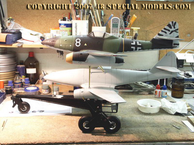
How stong these simple connections are shows after first assembly. When
lifting the whole constuction by the guidance aircraft and shaking it
slightly neither the bomb nore the trolley shake at all! Also you feel
the enormous weight of the model for the first time. It is 6kg by now!
Also you will notice that the center of gravity lies on the main axis
and a slight touch on the tail lifts the frontwheel of the trolley.
This means enough weight in both aircraft nose sections is necessary!
For testfitting I bolted the construction together with 1mm nails. These have to be replaced with screws later on.
Conversion of the wings and engines
The
conversion of the wings consist of two steps. First covering all wheel
wells and landingear boxes with plastic sheet. Second strenghtening the
structur of the wing itself.
Because both aircraft sit on each other like a sandwhich and are
connected by struts, this is not realy necessary from a static
viewpoint. But in prevention and from knowing the qualities of
plastics, I decided to put in a support, because it can not excluded
that the model will bend sooner or later.
Because the wings were apart at all and putting in an aluminum tube as
a mainbeam isn't much work at all, it is of use to practice such a
conversion.
The support beam is a 8mm aluminum tube, which is bent in the middle, so
the angle meets the wingform easy. At both ends the tube is flatened to
fit in the wingtips better. Both sides are approx. 25cm long and fit
right inbetween the connecting pins inside the wing. In some areas
sanding off uneven parts is necessary, to make the tube fit even into
the whole wing. At the main landingear box the walls need to be erased
a bit to make the tube fit in. When it fits to the wing it will be
fixed with clamps and glued with 5min. epoxy glue to the wing. The
glueing surface should be sanded beforehand to make the glue stick
better!
|
|
The position of the aluminum tube when cemented in.
|
The gap at he landingear box was routed. The 5min. Epoxy connects both parts for ever.
|
|
|
The main landinggear box was faired over with a 1.5mm plastic sheet, which was cut to shape and cemeted in.
On the original probably a simple metal sheet or plywood was bolted to it.
|
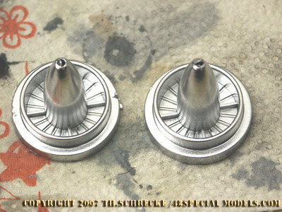
The jet engine intakes in correct paint sheme. The color is chrome from a spraycan. Quite convincing and simple!
What's still missing here is detail work and weathering.
|
The taken apart engines consist of just a few parts, intake, jets exhaust, lower cover, front cover and exhaust cover.
The intake is spray painted chrome by use of a paint can and after that
clear coated with JPS clear paint (the JPS Color paint doesn't destroy
the chrome effect!) at least it was weathered with a oilpaint wash. All
TL-engines were drenched in oil, this is why they have to have a oily
wash. The exhaust is painted with burnt iron polishing paint. This paint
has to be polished after drying by use of a soft brush or kitchen
towel. The effect is astonishing. After that spraypaint with clear for
protection again.
The intakes and exhaust covers will be painted too. The intake domes
are made of aluminum and were connected to the engine. They were
exchanged together with the engine! This is why most of them came
unpainted or only primed with RLM 76. Inside they were also bare
aluminum, this called for an aluminum polish finish too.
Into the cover of the intake dome the Riedel-Starter ring was put in
too. Therefore the less to small hole needed to be drilled wider. The
starter rings have to be placed in horizontal!
After priming the hole aircraft and painting the engine parts they can be assembled again.
After that the main connecting points on both aircraft need to be
settled. But this will happen after the trolley is completed first.
|
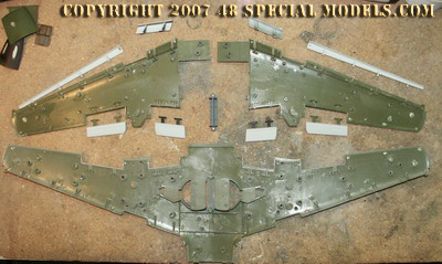
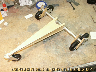
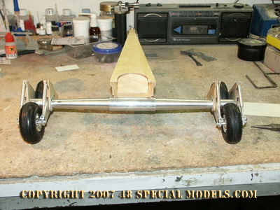
Making of the trolley
The trolley consists of a boxframe and an mainaxle, like to be seen on
the other Mistel 4 page. There are also the front wheel section and the
rato rocket.
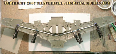
I started with the box frame, because it is made fast and quite simple.
Fotocopies of the parts were sticked to a plywood sheet and cut out on
the band saw. Onto the inside of the upper and lower frame plate a
smaller plate was cemented to serve as a conneting point for the side
panels. The mount for the frontwheel was made of a piece of massiv
multiplex wood, which was cemented to the upper panel, after the box
frame was cemented together.
For cementing a thickened epoxy resin was used, as usually used in RC
aircraft designing. This has a setting time of almost 60 minutes and
needs 24 hours to harden completly. You may use 5min. epoxy as well,
but the time for assembling will get short
eventually.
Epoxy glues have some edvantages. First they stick much better than
white glue. They add stability to the parts and you may simulate
welding seams too!
Therefore you put the thickened glue to a polybag and cut of one corner
as wide as you want your seam to be. You may also use a suringe too.
Then you go along the edge of the part adding a thin line of epoxy to
it. You can add the glue very exactly and also get the structure of a
welding seam.
The mount for the front wheel was made from a piece of
multiplex wood which was cut to almost fit the part and cemented in
place then. After hardening it will be sanded to fit on the belt sander.
In
the box frame rear the backing plate needs to be installed now.
Beforehand to the areas were holes will be drilled later and screws may
sit little plywood plates were added to give the right thickness and
hold.
For the rato-mount a 4mm iron wire was bent to
fit. Here the bending points need to be heated by a torch to prevent
breaking. The support strut going between both frames was screwed to
the framepieces. For this holes were drilled at the right points. They
also were cleaned from oil/grease to fill up the seams with thin
superglue afterwards. Also the screw heads were sanded to fit the shape
of the frame. In the end the screws vanish completely.
|
The axle
To
make the main axle a laith is necessary. Also I had made my self clear
how the construction needs to function. Thereby I found out that I will
be much closer to the original than I thought in the beginning.
Although the Mistel 4 never was built, there are only a few ways its
design could be realised. Seen from a technical point of view this
meant the function must work to find the right way of construction.
Today this is called reverse engineering.
I started with the mount for the main axles, which is connected to the
box frame end. Seen simple, this is just a tube. In the original a steel
tube with about 1mm wall thickness at all probably. Here it is an machined aluminum
tube with a centerhole of 14mm width. Drilling this hole bought
me to the limits of the capacities of my small laith. A 14mm drill
isn't only tick it is also long and hardly fitted to the machinery.
Fortunately I could manage to mount the part and the drill to the
laith, but no inch more! This was how an aluminum tube was made, the
main axle will fit in perfect later on.
The main axle was made as well as the 48scale version, in two
parts. First because it was to large for the laith and second
because it could not be fitted to the tube later on. At the inner end
the parts are made tight fitting so they slight smooth to the tube. The
inside ends have a thread and nut mount so they can be connected by
screwing them together. This is made a little shorter than the tube it
sits in, so it can be tightened by turning. The big advantage is you
don't see the kind of connection from outside and no additonal
secureing is necessary. Also the whole construction can be dissasambled
in seconds by hand.
 |
 |
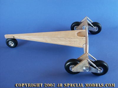
| The trolley without primer.
|
Back view of the trolley without rato rocket and parachute box.
|
|
|
This picture shows the geometry of the trolley perfect.
|
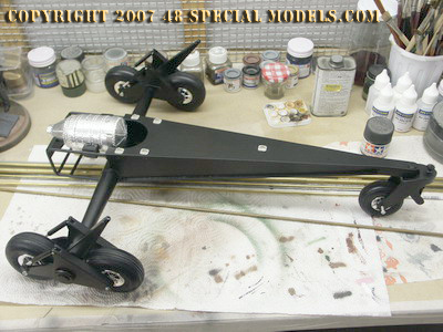
The primed trolley with added rato rocket and fittings.
|
|
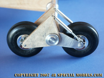
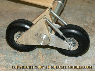
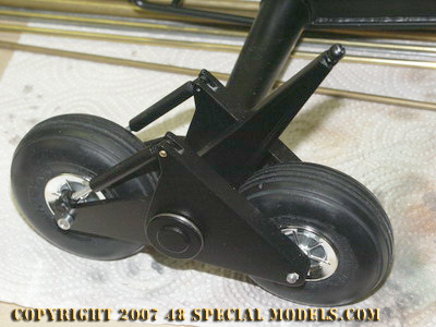
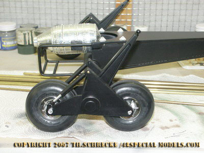
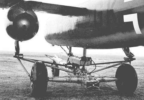
The main axle and wheel
On each side of the axle a double wheel "runner" frame is
mounted. These runners run free on the axle. They can be turned around
the whole axle. The rear wheel is mounted to a swing too, which is held
by a shock absorber. This makes sense and helps keeping distance to the
ground. On the original these shock absorbers could be adjusted to the
total weight of the several mistel versions. On the model making them
was a challange.
I had to develope the complete design and function myself, because I
didn't want to install a machined mock up piece. I needed shock
absorbers in 1/18 scale that worked and fitted to the design also! You
can't buy them in the hobby store around the corner, so I had to make
them.
The prinziple is simple. A rod goes to a spring and
compresses it in its tube when a force applies. Constructing this in
real and four times wasn't that simple. First you need the fitting
springs. Where can you get them from? Quite easy from a ball pen! The
force adjustment works by cutting the spring to fit.
After that the shockabsorber housing is made on the laith. And how are
they fixed to the trolley? Well when buying the wheels I also got some
forkheads and some screw in flanges. The flanges consist of a M4 screw
bolt and an eye on one end. These can be screwed to the absorber tube
and make the upper end of the shockabsorber. The lower end is an
aluminum rod with a M3 thread on which a cut to fit forkhead is screwed
on. The rest is tiny work which took me two complete Sundays at the
laith. Ready are the shock absorbers!
The swings were cut from 3mm aluminum sheet material and
sanded at the belt sander. All parts were sticked togeter with
doublesided tape and sanded at once as well as drilled. This helps
drilling all holes exactly to the same spot and getting the same shape.
The opposite part was made from three parts cut out of
plywood. These also were sticked together temporarily with tape and
drilled, cut and sanded to fit as well. After that the parts neded to be
seperated again, which wasn't that easy with wood than it was with
aluminium. The middle piece was cut out then to give way for the
absobers and swings. After that the parts were cemented together again
with epoxy glue. After setting all parts were finally sanded and test
fitted. After that they were primed with as fast sanding primer for
wood, which closes the surface and hardens it too. This lets the parts
become sanded smooth and makes them fit exactly.
|
|
The testfitted swings and shock absorbers.
|
For keeping the distance between both frame parts an
aluminum tube was inserted.
|
|
 |
The final configuration with the wing support struts.
|
The positioning can be seen good here in the side view.
|
|
|
The absorbers have been fixed in place with 1.2mm screws
|
|
|
Wheel axles and deviders
The
wheels axles are made from M4 thread rods. By help of nuts or nut tubes
they are fixed to the swings and frames. The wheels run free inbetween
them. The axles will be later cemented to one side of the wheel mount,
to prevent loosening when working.
To keep the distance between both wheel frames and to install the wing
support strut later on, a 22mm wide spacer tube was made, which is
placed loose inbetween the wheelframes onto the main axle. For
secureing the wheel frames onto the main axle an end plate with a screw
bolt was made and screwed on. These prevent the wheel frames from
falling off the axle without blocking them.
All together constructing the main axle and wheel mount was quite a
challange. Without a precison laith it would be impossible to make. The
more satisfying it is to see the whole thing work like the original and
show a realistic effect.
The
wing support struts are made from a plywood sheet which was cut and
sanded to fit. On the outside edges a 2mm polystyrene strip was glued
on, which simulates the profil. Who has got time and machinery may rout
this piece from a aluminum sheet as well too. The other way is much
faster. After sanding and fitting a 3mm hole is drilled into the top
end. Here a thread rod of 1cm length is cemented in first and then
first a nut and following a 5-7mm long tube piece will be screwed onto
it. The tube piece works as a spacer and simulates also the explosive
bolt placed here. After all struts are adjusted finally it can be fixed
in place with a drop of superglue.
|
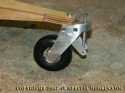
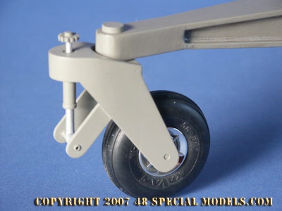
Front wheel mount
The
front wheel mount was related to finding the fitting wheel first!
After that the design could be made. Obviously there are differences to
the original wheels. But so I have had only the choise between buying
one or makuing it myself, buying was the more easy way and cheaper too.
For checking the fit the bought wheel would be good enough at all. If
it wouldn't fit a selfmade wheel was still an option.
|
|
| Front wheel mounting with absorber.
|
The final front wheel mount.
Only the rim needs to be changed!
|
The
from wheel mount was made from several pieces and consists mostly of
aluminum. From a block of aluminum the upper part was routed. To its
sides the axle mounts were screwed with two screws each, which were later glued
in, filled with putty and egalized. As an axle a M4 threat rod
was used. The holds for the absorber are also made from aluminum sheet
and screwed to the side parts from the inside with one screw on each
side. The absorber this time ia a mock up without function. It is
screwed to the upper part by a thread. On the original it makes the
front wheel run straight and prevents vibrations (similar to the wheels
of a shopping cart going fast) as soon as the trolley takes on speed.
The adjusting wheel on top is made from a piece from a disposal zipper,
which regulates the flames hight usually. It fits perfectly on the
absorber to simulate the control wheel. I only needed to drill an M3
thread to it so I can screw it to the absorber and secure it with a drop
of superglue.
Into the upper block part a 6mm hole was drilled, to
mount it to the trolleys box frame. Also a 6mm hole was drilled to the
box frame. I also made a two parted screw bolt, which fits
through both holes and is secured from below. This makes the wheel turn
free without loosening the screw. On the original the design may have
looked different, but it sure worked the same way. There may be assumed
that a ball bareing was installed inbetween trolley and wheel well. How
the construction may have looked like is unknown. For sure is only it has to take large weights (about 17t) and forces und would
have been a big dimensioned part.
|
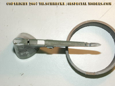
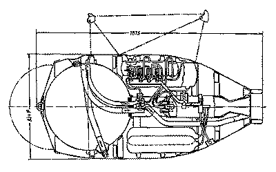
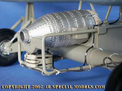
Rato rocket (Starthilferakete) Walther HWK 109-501
The so called Starthilferakete of typ Walther HWK 109-501 is an important part of the whole Mistel design. Without it the Mistel wouldn't lift up at all! The HWK
109-501 had had 1500kp of trust for about 30 sec.. It also shortened the needed runway distance a lot!
|
|
Walther
HWK 109-501 with 30 sec. working duration.
(Source:
"Die deutschen Raketenflugzeuge 1935-45", Motorbuch Verlag)
|
Cut away drawing of Walther HWK 109-501
(Source: "Die deutschen Raketenflugzeuge 1935-45", Motorbuch Verlag)
|
The Walther
HWK 109-501 rato rocket is much bigger than all other known German
ratos, as they have been used for example on the Ar234B (HWK
109-500).
Attached to the rato usually was a parachute pack for recovery, which
brought back the rato after use savely. It is unknown if the parachute
pack was installed to the rato here too. But it can be assumed that
only complete ratos were attached.
This part is another challange , because it has to be made from scratch
in complete. In 1/18 scale it also shows a lot more detail as in
smaller scales. The basic shape was machined on the laith again, from a
piece of resin cast into a tube shape. It had to be done in two parts,
because of the size and the shape. This gives the chance to machine it
hollow inside, to reduce weight a bit.
|
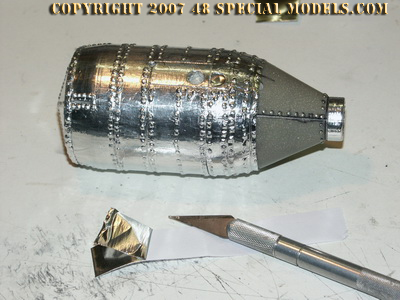 |
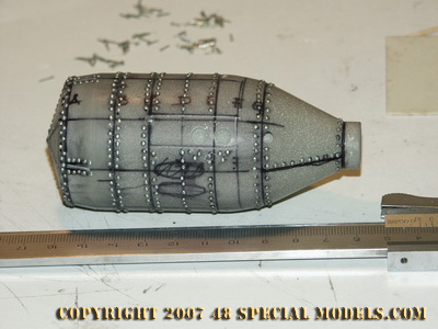
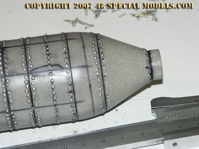
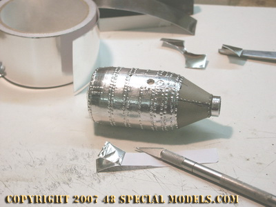
The rato rocket was machined from a resin cast block and the bolts simulated by 1mm nails added to the surface.
|
Useing aluminum tape, as usually used for roof insulation, to give the surface the realistic metal finish.
|
|
|
On the original too the bolts didn't sit in a perfect row all times!
|
Applying the aluminum tape takes time and practice, but it rewards with an astonishing metal look!
|
|
|
The eyes are bent from 0.8mm brass wire and are attached in a slope to the parachute pack.
Made from 1mm brass wire are the hooks,
that are put in place her for testing.
|
The hooks hold the parachute pack like the original only at the eyes! |
|
 |
The
completed recovery parachute pack is only hooked to the rato here, like
the original too! It can be removed any time, because the rato itself
is just hooked in its cradle too.
|
One
of the hooks the parachute pack is fixed with. It hooks to the eye on
the pack and rests with the other end to a hole in the rato.
|
The
part was made first from a resin cast rough material. I used a standard
resin I use in my model kit production too, adding some filling
material. This makes the resin easy to machine and also prevents
overheating the massive block while setting.
I cast the material to an ordinary 0,2l polystyrene drinking cup
and let it set. The cup can be peeled off then and ready is the rough
piece. Due to the cups shape the part can be placed in the laíth
easy and save.
Now the piece needs to get an even shape to make it run smooth. Then
it was machined to fit the original shape. So both ends are conic I had
to make it in two seperate parts, which were cemented together with
superglue later on.
By the help of a marker I marked the rivett lines. Engravings and slots
were added too while machining. For each rivet a hole was drilled by
hand! This makes 88 holes per ring on the large diameter. Several
hundred 1mm nails were nailed in and secured with superglue. It drove
me crazy!
The exhaust nozzle also was routed conic,
like the original. The tankhood and armatures also and the sheet
edges running vertical were engraved by hand.
The
fun part came later on. By accident (I insulated my attic) I found a
aluminum foilage tape, which is normaly used to seal rock wool
insulation. This very fine tape sticks like hell to anything and can't
be torn of in one piece anymore. Its main advantage is it is made from
aluminum foil. Some modeller may know something similar called Bare
Metal Foil. The main difference is it is much cheaper. I got a roll in
a discounter for 1,79Euro. It has 15m of tape and will last for a lot
more models too. When working with this tape I had the idea to test it
on the rato rocket body. It worked excellent.
The
resin part was first cleaned from oil and the foil cut to fitting
stripes. When applying the tape it is important to do it step by step
and useing the right tool for pressing the tape to the surface. Some
dentists tools work well and a soft piece of wood too. I used both
depending on what worked better in some situations.
It
needs a lot of patience to apply the tape and I still got it from
drilling the holes and putting in the nails before. But applying the
foil gives you back more! The surface instantly gets a perfect metal
look. All nailheads morph into rivets and by polishing the surface
gets a perfect finish.
For fixing the rato roket to
the trolley on the original there where bolts on both sides which were
used also for storing on the transportation carrier (see picture
above). On the model two screws from a computer rack were used. Usually
harddisks are screwed with them to the computer. Here they get a more
exciting job. The screw heads are very flat on this kind of screws and
they have a machine thread too. So they can be screwed to the holes
(without drilling a thread) on the rato rocket side as well as the
screw head helps to hook it into the rest on the trolley.
The parachute on the rato is of no use on the trolley, because it is
used only for recovery when dropped from an aircraft. Therefore it is
not clear if it was installed at all. It is possible that it was simply
removed to save weight. It is also possible that the rocket and
parachute were a unit in function and needed to be kept togehter to
work propper or it was easier to leave it on than removing it simply. I
just like it better than the naked rocket, but left open the option
to remove it by giving it the same connection by hooks like the
original. These can be taken of any time.
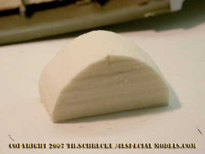
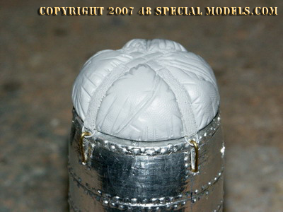
The parachute pack is made in several steps from an
epoxy putty. First a core piece is sculpted. A flatend sphere about 2/3
of the final size. This was let set. Onto the rato rocket a plastic
foil was stripped where the parachute block would be placed later. It
served as a seperator. Then the epoxy ball was pressed on to. This gave
it the exact fitting shape!
Then the detailed
surface was sculpted on. Here the belts have been spaced out and
instead of them a 1mm deep gap was sculpted. Here real belts were glued
on later on, made from a cotton tape. The belts were glued around the
lower side too and a ring was attached in before on each end.
These
rings are also on the original. They take the hooks that hold the
parachute pack in place. The parachute itselve is connected to the ring
in the middle of the rato front end. By a rope that is connected to the
aircraft the parachute pack is opened and the parachute is ejected by a
spring out of the pack. The rato lands on the ground an can be used
again. This principle is still used today on Space Shuttle and Ariane 5
Boosters!
|
Rato mount / parachute box
From
a 6mm iron wire I bent both tube frames. Doing this the bending edges
need to be heated up several times to prevent breaking. Also after the
final shape is reached too. To get tentions out of the material. The
suport tubes are cut from iron wire too and filed to fit to the frame
by screwing. Who preferes to weld or soulder may do so instead, but the
parts can not be taken apart anymore then!
The tube frame needs to be fitted to the trolley now. The upper tube
ends will be placed into a hole in the trolleys box frame. The lower
ends go to a depression on the axle mount blow and will be screwed to
it.
Like all parts they will be test fit first only. To have the chance to
remove them always for testfitting other parts and for painting later on!
|
|
The rato is put in place loose only. From a block of resin a mount was routed and screwed and glued to the frame.
|
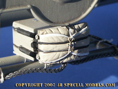
Rato and parachute box in place. Missing are the wireing and the parachute rope on both sides of the axle.
|
|
|
The
parachute box in place. It is fixed with epoxy glue. after setting the
hinges can be mounted on its lower side. They simulate the way it was
fixed on original.
|
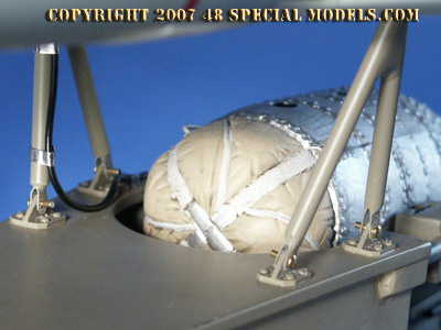
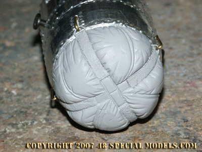
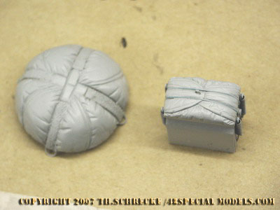
The rato and trolley parachute pack.
They both were sculpted from an epoxy putty and decorated after setting with real straps of cloth.
|
|
 |
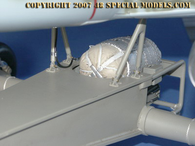
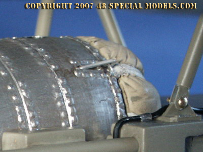
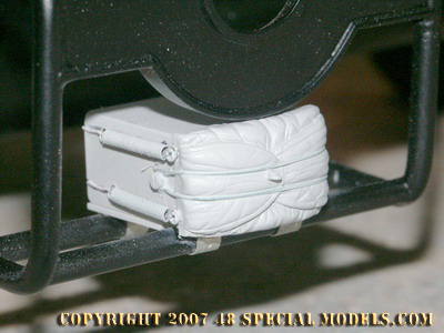
The finished parachute box. Good to be seen is the splint, made from wire. This was ejected through a bowdenwire which is installed on top of the box.
|
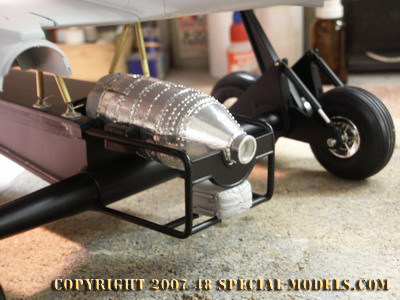
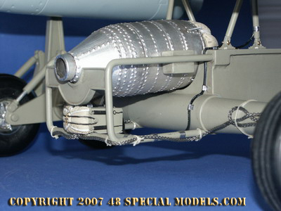
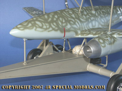
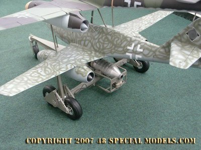
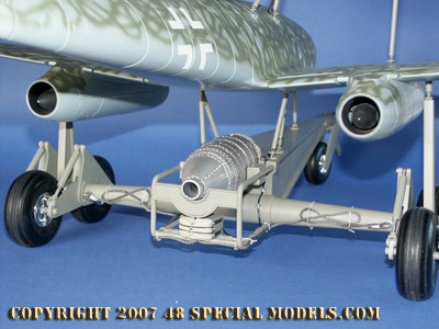
The rato in its final position. |
Into
the trolley tube frame a board is placed now on which the rato nozzle
sits. Also another bulkead is cemented into the trolleys box frame end,
on which the rato front end rests. As well as a mounting device for the rato
is installed to the tube frame where the ratos mounting bolts will
rest. This way the rato can be hooked in like the original. The
bulkhead at its front end prevents the rato from flipping over (like a
firecracker).
Below the rato two support struts are installed to take the parachute
box. This box contains the break parachute, which will be ejected
automatically after the mistel has left the trolley. This is done with
a rope, as usually on all parachutes, which draws a splint from the
pack and lets the parachute eject from its box by a pre-tightened
spring system. The original principle is as easy as simple too and
completely mechanical. It can be done on the model therefore quite well.
The
parachute box was cut from a block of resin and sanded to fit. On the
backside a 1.5mm thick styrene sheet was glued which overlaps about 1mm
on each edge. To this plate the parachute package bag was sculted with
epoxy putty. This can be done perfectly with the putty. And by
pressing on cloth texture and other structures a realistic surface can
be modelled. By use of dental tools and a bit of water all shapes are
sculted. As a pattern for copying a picture of the existing AR 234 V1
parachute box is used.
After setting of the epoxy putty three 1mm holes were drilled to each
side of the box. Into them some subminiature screws were screwed (like
to be seen on the picture). Another hole was drilled into the pack bag,
were later on the eye for the splint is added. Around the middle screw
a 1mm wire is tied, which goes over to the other side of the pack.
To the other screws on both sides some springs are attached, which are connected
to the sping on the opposite side of the pack. I took real springs from
my large collection of kept parts (it is good to keep everything!).
These probably come from an old typewriter or any other similar
electronic device.
Who has nothing like that, may bend them from copper wire. Both
springs ware tied together with a piece of electrical copper wire.
Doing that most simple is to connect the wire to the spring first and
measure the needed length. One cut it to length first and twist
the ends to the other spring. To the back of the parachute box two gaps
are engraved, where the wire will rest later. Then connect the springs
to the screw heads and they will be tightened a little. This also shows
the correct way of the construction and how it worked too. In real the
springs gave the tention to eject the parachute. As soon as the splint
is removed they through out the parachute pack and the parachute can
inflate.
|
Back view of Ar 234
trolley of the second version with parachute box.
|
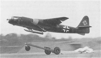 |
Start of an AR234 from its trolley.
Good to be seen is the way the parachute inflates.
|
Picture source unknown, probably Bundesarchiv.
|
Painting and finishing
All
parts of the trolley will be primed. Therefore they need to be prepared
in the usual way. All parts will be taken apart first as far as
possible. The metal parts will be cleaned and primed with a special
aluminum primer. The wooden parts are sanded fine and spraypainted with
a layer of filler from the spray can then, to egalise any uneven
surface structures. This will be repeated eventually several times, if
necessary.
Take care not to apply any
paint to the connecting surfaces, to prevent problems when assembleing
again. Cover these areas with masking tape to protect them.
After
having dried completely the first layer of paint is applied. Here a
layer of black from a spray can. This will be sanded again with 600
grain wetsanding pads and cleaned again afterwards. After that the
final RLM 02/1 gray, the color of all prototyps, is applied in the
manners of modelling. Ageing and weathering follows after reassembling
the trolley.
Notice
please, that the trolley is the only part of the Mistel which has been
reused several times, although this is a fictional model. Otherwise the
bomb was a old or wracked aircraft body which was modyfied, as usually
all Mistels were. A warhead was attached that maybe has a different
shade of colors and nobody took notice of that too. It is also possible
the bomb had had a simple RLM 76 light gray primer color over all, for
corrosion protection and simplyfied camoflage.
The guidance aircraft, in opposite, is an often used combat aircraft
which was modified for this purpose. Depending on the type, if A1/A2 or
U2, this can vary from its paint sheme. A1 and A2 aircraft have been
relativly new and in perfect optical condition regarding the colors. Of
the U2 aircraft only 2 prototyps existed, the V555 and V484. Of both of
them photos are existing and these may be used as a reference here.
The model I made is a A1/A2 version and will be painted in the colors
of a late paint sheme, because the Novotny aircraft never was a Mistel
aircraft for sure.
The offical Paint Shemes Order
for this period were RLM 81 and RLM 82 for the upper surface of the
aircraft. The manufacturers delivered all Me 262s in a RLM 76 light
gray primer color as a corrosion protection. Onto this a camoflage was
added. The order also says that the truth of color in comparison to the
sample wasn't controlled at all (which means if belonged to the painter
what he thought was right!) which leads to the assumtion, that many
aircraft didn't meet the order given, because the right amount of
colors were lacking or were mixed with others to get enough paint to do
the job. There is also a order in the same order that says that old RLM
70 and RLM71 colors can be replaced by RLM 81 or RLM 82 if left over
stock has been used up! This means the combination of these four colors
was allowed, so there might have been some strange combinations
possible on one aircraft indeed.
Photos of originals show that many aircraft were primed only in RLM 76
and had had added on a meandering in green color onto the fuselage or
the standard paint sheme (upper side RLM76, lower side RLM 81/82 splinter camo) was added with a veriety of other camoflage patterns. Here can be worked in each case only be reference to photos!
So the Mistel 4 was a project only, the paint shemes are only limited by the offical Paint
Shemes Order and the known facts on painting aircarft during the last
days of war. In general any color sheme that fits to the time frame is
possible.
|
|
The
bomb was painted RLM 76 in complete first and after that meandered with
RLM 81. The jet intakes are bare aluminum polishing colors.
The trolley was painted in RLM 02/1, as all prototyps were.
The support struts also.
|
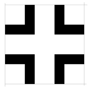
Pattern for the so called "Balkenkreuz" on the wing top
(In original size 630mm wide).
The complete markings and insignia were done in size of the original, depending on the order and then scaled to fit and printed out.
|
|
|
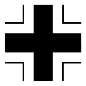
The "Balkenkreuz" for the fuselage sides
(In original 800mm wide).
|
The "Balkenkreuz" for the lower wing surface
(In original 800mm wide).
|
 |
|
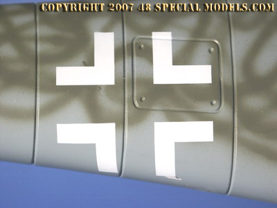
Cut from a masking tape a spray paint mask was made and spray painted on with an airbrush.
Notice the change of shape caused by the rounded fuselage!
|
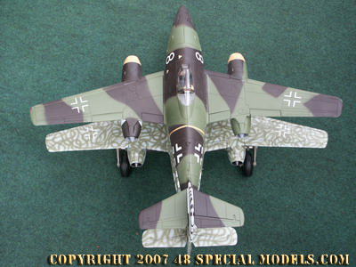
The
whole mistel from above. The guidance aircraft is still in the
delivered paint sheme (RLM 81/82) and will be repainted later.
|
|
 |
The mistel seen in daylight. The swatikas are removed here, but exist on the model for historical correctness.
|
The guidance aircraft will get a other paint sheme later, because this doesn't fit to the model at all.
|
Painting of the guidance aircraft
I
couldn't decide which colors to use on the guidance aircraft for a long
time. During that time span the new 21st Me262 came out having the
camoflage sheme which fits this model perfect. But the model itself
doesn't fit to the Admiral Toys model which is differing in detail a
lot and doesn't fit together in the Mistel constellation. So I didn't
want to start from the beginning, I decided to use an older paint sheme
used on the first operational Me 262 A1s. It consists of a RLM 74
darkgreen and RLM 75 mid gray on the topside. So this was a Me 262A1 of
the first series no bad idea at all.
After a series of paint tests and checking a nice book on the Me 262,
with good color prints on the painsjobs for reference, I came over a
color sheme in the book wich was explained as the one with the colors
mentioned above, but used instead of RLM 74 dark green as dicscribed
RLM 82 green as a top side paint. So I couldn't check at all if this is
a misspelling in the text or misprint in color, I decided to follow the
printed color, because I simply liked it more. So this isn't in
opposite to the offical paint orders given, it is a possible paint
sheme and because it was a project only, useing up old paint can be
assumed.
The resulting paint sheme of the guidance aircraft is as follows:
Primer/ lower side: RLM 76 light gray
top side: RLM 75 mid gray /RLM 83 green splinter camo on wings and clouds on the fuselage
Before
painting preparations come first. The construction was less converted.
Including the stabilizer and elevators conversions as described above.
So this needs not to be explained again. The jet engines were treated
as described before too. Only the fuselage wasn't modified, but
cemented and the gaps were filled with putty. After that sanding was
done and everyting primed.
Here the cockpit and canopy needed to be masked off by tape or taken
off completely and the cockpit simply taped over with masking
tape. Now the complete aircraft was primed. After that it was
sanded with 600 grade wetsanding paper and cleaned again. Then the
lower side was spray painted in RLM 76 light gray. This was applied
around the wing edges and on the whole fuselage. After that had dried a
splinter pattern in RLM75/82 was applied to the top of the fueselage,
which disapears in clouds to the lower areas. The upper wings have been
painted in the calssic splinter pattern of the paint order.
As on the bomb before the insignia will be spary painted on then. So
these are similar to the ones on the bomb, the masks made already can
be reused her. The lost fuel and safty markings weren't added to all
aircraft at all. Mostly only on new ones in manufacturers first paint
shemes. So they can be missed out.
|
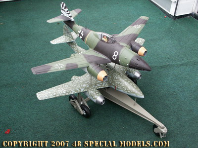
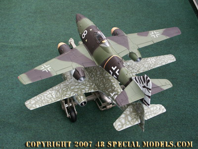
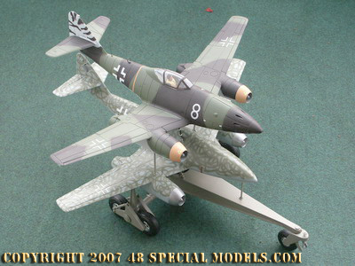
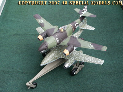
Beautyshots
|
|
View from the right side.
|
View from the left side.
|
|
|
The top aircraft is not finaly painted here!
|
View from above left.
|
|
|
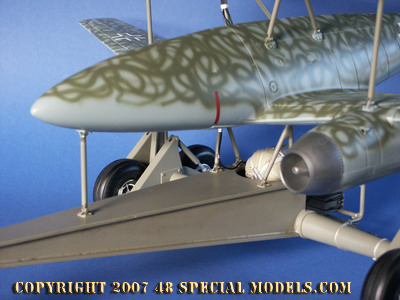
Detailview of the rato rocket and break parachute construction.
|
The rato rocket and its wiring.
|
All pictures on this page are copyright protected.
Use without written permission prohibited!
|
|