Facts
on the

|
At
the end of WWII the leaders in the RLM ordered more so called
"Mistelgespanne"
attacks against large targets like bridges and ships. For that task
investigations
on development and logistics of suitable airframes were made.
Besides
a lot of other composite aircraft designes the Mistel 4, a composite of
two Me 262, was investigated.
|
|
|
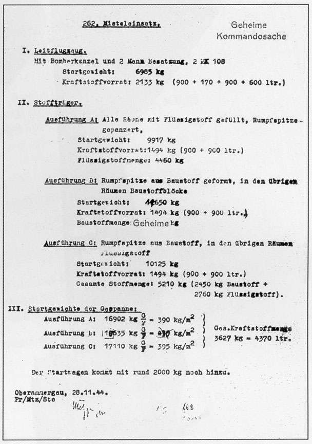
Table
taken from:"Mistel - German Composite Aircraft and Operations 1942-1945"
|
|
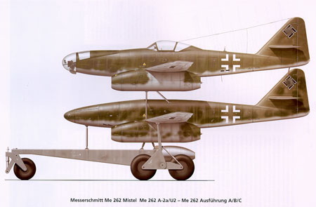
The "Gespann"
The
Mistel 4 is a composite aircraft, consisting of a explosives filled Me
262 and a so called "Führungsflugzeug" (guidance aircraft) Me 262
A1 or A2/U2 which was mounted on top. This composite aircraft didn't
make
it far more then to the design stage and never became operational.
The
reason for its development might be the fact that all composite
aircraft
were quite vulnerable during the target approach run, because they
weren't
fast and manoeuvrable. Also the new jet engines made a compact
design
and a higher payload possible. As well as they were the reason
why
this project never made it . There were to less of this engines
available
at that time and they consisted of precious and needed materials, that
couldn't be wasted.
The
developement was almost completed by the end of the war and
production
could have started soon. The war situation and strategic reasons
may have prevented its use.
|
 |
 |
| Me
262 A2a/U2
- Me 262 A |
Me
262 A1/A2
-Me 262 A |
|
The
flying bomb
Me 262 A
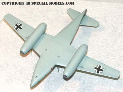
The
Mistel 4 consisted of two Me 262 mounted on top of each other. The
lower
Me 262 A was modified to a so called "Sprengstoffträger"
(explosives
carrier).
The
complet front section, up to the wing frontedge, was designed as a
warhead.
So this was a seperate construction section at all, the warhead could
have
been built as a seperate section and fitted on. For example the whole
section
was planned to be made from explosives, without any wooden or aluminum
fuselagecovering. More explosives, liquid and solid ones, should be
placed
in the aft fuselage.
The
lower Me 262 should be older ones or especially designed ones made from
no metal materials like wood. There have been tests to build the Me 262
fuselage particialy and in whole from wood to save precious aircraft
aluminum.
|
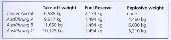
Table
from: "Mistel- German Composite Aircraft and Operations 1942-1945"
|
The
Guidance
Aircraft
For
a guidance aircraft the Me 262 A1 as well as an A2 or the prototypes
unter
testing Me 262 U2, with glazed nose section, were considered. The Me
262
U2 existed only in two prototypes, with slightly differing glazings, by
the end of the war. The front was designed to carry a bombardier who
coordinated
the drop of the wapon. It can be assumed that for weight reasons the A1
or A2 versions would have been preferred.
On
the flight qualities of the composite can be speculated only. Special
problems
may have occured on the handling of four jet engines at a time. Because
it is known that even two jet engines kept the pilot bussy during
flight.
Maybe this is the reason for the U2- version considerations?
|
|
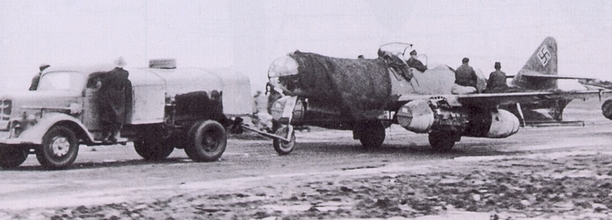
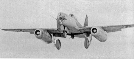
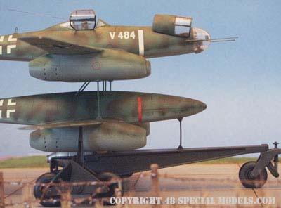
The
Me 262 A2/U2 V484 towed by a tanker. Watch the cover on the nose
section.
(Picture
by: "Mistel- German Composite Aircraft and Operations 1942-1945")
|
|
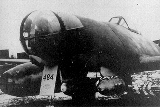 (Picture
by: "Me 262", Aviatic Verlag)
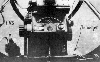
(Picture
by: "Me 262", Aviatic Verlag)
|
|
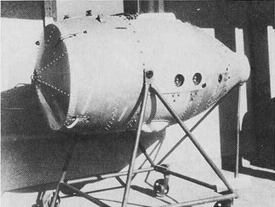
View
of the first "LOTFE-Bombers" Me 262 A2/U2,
Prod.-No.
110484 with two SC250.
|
The
LOTFE mounted in the V484 |
|
|
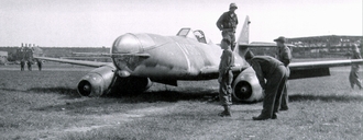
The
second modified aircraft, Prod.-No. 110555 (V555) with Antennas.
(Picture
by: "Me 262", Aviatic Verlag)
|
The
V555 shortly after lift off.
Watch
the front section is clearly different in color.
(Picture
by: "Me 262", Aviatic Verlag)
|
|
|
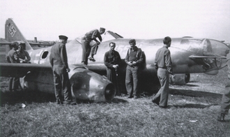
One
of the last pictures of the V555
after
a belly landing on 08.May 1945
|
US
Personnel checking the aircraft after it was landed on airfield
Weimar-Nohra
by Oblt. Benz almost without damage. |
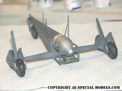
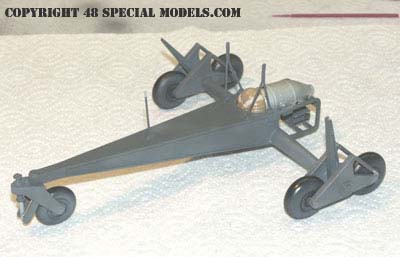
The Trolley
The
trolley with booster is most interesting. Here a Walther HWK109-501
rocket
booster should have been used for. This made a reconstruction of the
center
structure necessary, to fix the "Starthilferegrät" (booster) to
the
trolley. Below the booster the break parachure box was placed. The rest
of the trolley was similar to the Ar 234 and E377/E377a trolleys.
Because
of the higher weight and the minor wing size the boosters were needed
to
speed up the Mistel during take off.
|
|
Walther
HWK 109-501 with 30 sec. running time.
(Picture
by: "Die deutschen Raketenflugzeuge 1935-45", Motorbuch Verlag)
|
Scheme
of the Walther HWK 109-501
(Picture
by: "Die deutschen Raketenflugzeuge 1935-45", Motorbuch Verlag)
|
Colours and
Insignia
The
painting and squadron affiliation are pure fiction. It can be assumed
that
the guidance aircraft was painted in the colours of late war camouflage
shemes. The bomb would have been covered, if at all, with an improvised
camouflage. Maybe a light grey corrosion protection would have been
sprayed
over with a random green or brown camouflage pattern. It is also
possible
that it lacked any painting at all and was used in bare metal.
|
|
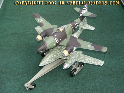
|
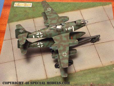
Mistel 4
- Me 262 A2a/U2 - Me 262
|
|
Picture
from: "Mistel- German Composite Aircraft and Operations 1942-1945"
|
|

|
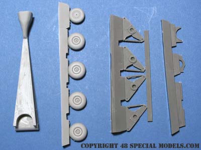
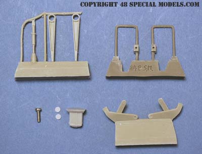
| The
kit consits of 52 parts: |
|
|
|
Mainframe,
Set of Wheels, Suspensions,
Booster
Support Parts
|
Main
Axles, Angles and Plates, Handwheel
|
|
|
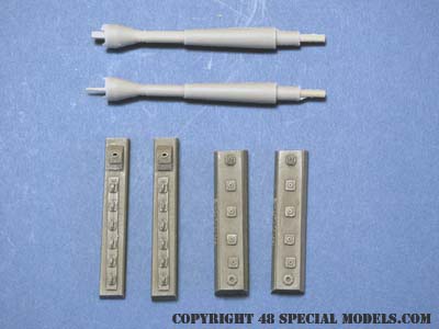
Schock
Absorber, Support Struts, Booster Frame, Screw,
2
Styrene Plates, Parachute Box,
Front
Wheel Suspension
|
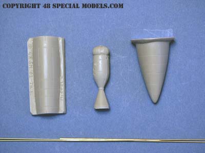
Cockpit
Cover, Booster, Fuselage Nose,
Brass
Wire
|
|

Model
made and photographed by
Thorsten
Schrecke
This
model is built from historic informations.
The
markings meet the standards of its historic origin.
They
do not reflect the political oppinion of the modelmaker in any way!
|
|
|
|
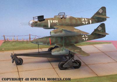
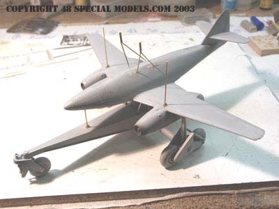
Sideview
of the Mistel 4 in all of her pride.
|
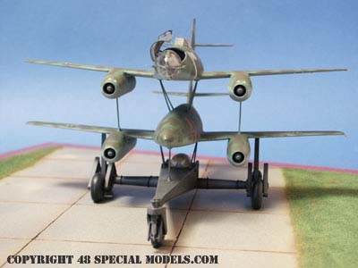
Frontview.
Good to be seen the supportstruts. By the way the upper plane is just
put
in place and not cemented.
The
tension of the struts hold it perfect.
|
|
|
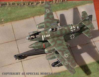
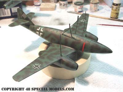
Right
view.
This
shows the camouflage pattern very well.
|
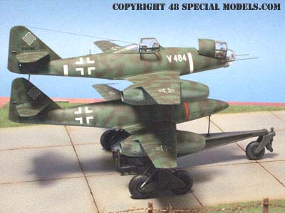
Left
view from above.
The
cockpit hatches can be shown in open or closed position.
|
|
|
|
Sideview
from the right side.
|
The
bombardier figure comes with the Dragon kit.
The
pilot is from the Tamiya kit, but the Dragon kit also
contains
a nice pilot figure!
|
|
|
|
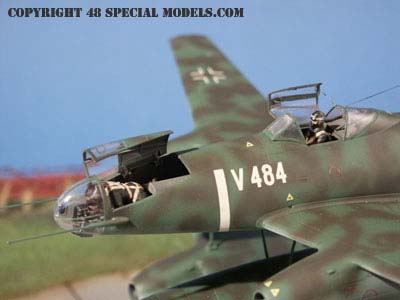
View
of an besides standing observer, it seems.
|
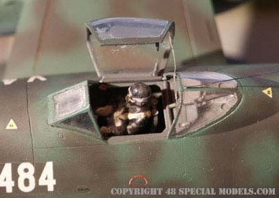
The
bombardiers compartment is well detailed,
although
it can't be seen much here.
The
bombardier figure is only put in place, not cemented!
|
|
|
|
The
Tamiya pilot is more of the size of a Japanese than a German pilot, but
he has an oxygen mask and can be placed on top of the belts
without
looking to tall.
|
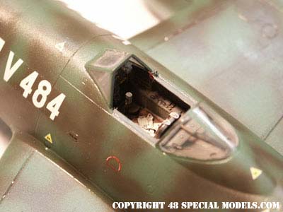
The
cockpit without a pilot. The belts are put in place and the pilot is
placed
on top of them, without guleing.
This
allowes to still change the diorama situation later on.
|
|
|
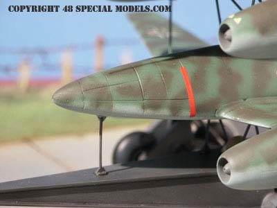
The
warhead of the "Sprengstoffträger" Me 262A.
The
red "bellytie" is a marking of the connectingpoint
and
a warning sign too.
|
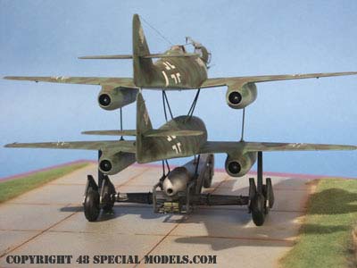
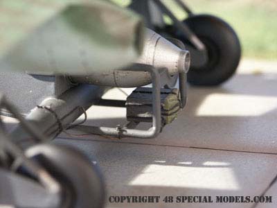
Backview
with boosters HWK 109-501 and the parachutebox.
|
|
|
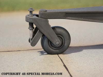
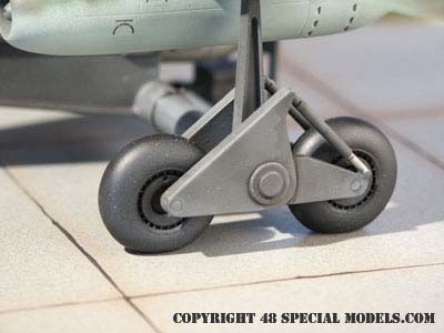
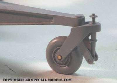
The
frontwheel of the trolley.
The
shock absorber keeps the wheel from lurching at highspeed.
|
The
parachutebox for the breakparachute.
The
ropes to the left and right hold the parachute when ejected.
|
|
|
|
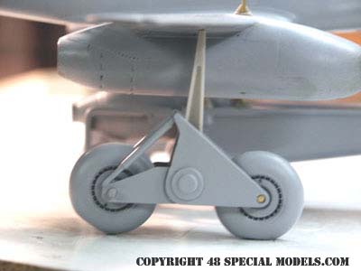
The
maingear with its shock absorbers and wing support strut.
|
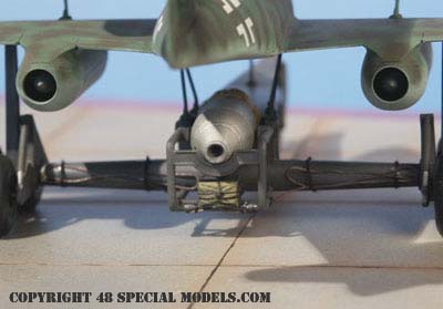
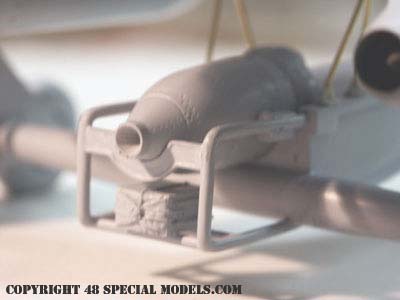
Detailview
of the parachutebox and booster. The wire goes below the box and is
attached
with thin ropes to the frame.
The
ropes are predetermined breaking points.
|
|

|
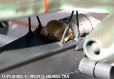
Detail
of the booster and mainstruts.
The
parachutepack on the booster is still mounted but off duty during this
operation.
|
Details
that make a diorama.
Handmade
barb wire fence to keep out the sheep.
|
|

Model
made and photographed by
Thorsten
Schrecke
|
|
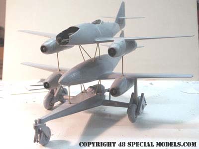
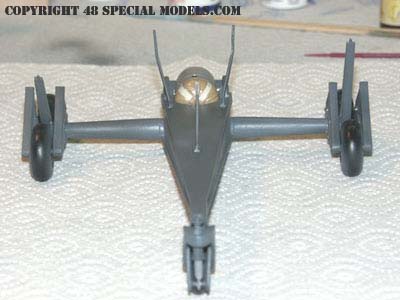
Complete
view of the Mistel 4 model under construction.
Both
Me 262 are from Dragon /Italeri. The nosepart of the lower plane comes
with the conversion kit, as well as the cockpit cover.
|
The
composite without guidance aircraft. Clearly visible are the shapes of
the struts.
|
|

|
|
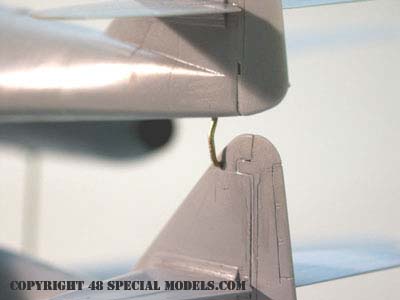
Detail
view of the tail support strut.
|
Frontview
of the Mistel 4. Good to be seen the positions of the
struts
on the trolley as well as on the bomb plane.
|
|
|
|
The
front wheel of the trolley in detail.
|
The
lower support struts in detail.
|
|
|
|
Position
of the wing support strut at the trolley.
|
Detail
of the booster rest and parachute box.
|
| |
|
|
|
| |
|
|
|
The
painted trolley with mounted booster
HWK
109-501.
|
The
lower side of the "Sprengstoffträger". Insignia would have been
the
only markings attached here ( besides some savety markings).
|
|
|
|
The
Sprengstoffträger with all markings. The red ribbon is fictious
and
marks the mountingedge. It could have been a security marking. A
warning
of the high explosive load.
|
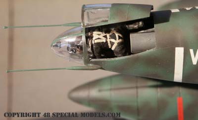
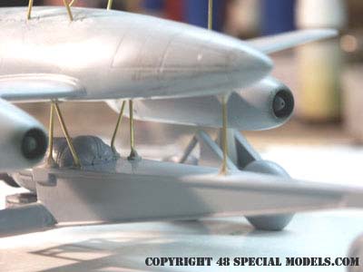
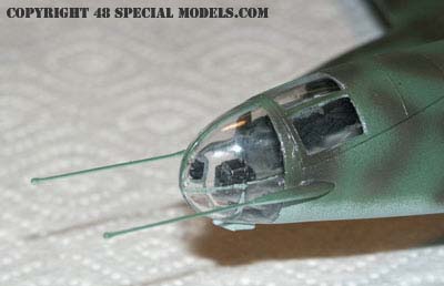
The
Bombardiers compartment
with
antennas. These consist of 0,8mm wire. The tipcaps are a drop of
superglue!
|
These
pictures are helpful for building the kit, because they show the
support
strut positions and other details very well.
|
It can be done larger too!
I made this model in 1/18 scale too!
This time with the Me 262 A1 Version on top!
Details on making it can be found on the Making of -page, at the link behind the picture!
Just click on the picture!
|
|
| 48 Special Models
feels complimented to be copied by a known injection mould
manufacturer.
Unfortunately not perfect. A more careful investigation would have been
of some help. Because although the Me 262 Mistel only was a project, it
still is subject to some fundamental, constructive requirements. Sure
one
or the other point may be worth a argumentation, but some points are
pinned
to well-founded reasons that make the design. By use of the photographs
below and the numbering I will show up some of the main mistakes. |
 |
|
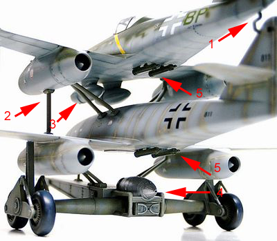
| Point:
1.
On the mount at the tail no data exsists. Truely it is a design of my
own.
Good noticed.
2.
The struts are in the right place, but streamlined struts always were
fixed
ones. They couldn't fall over! The struts on the wing need to fall
over,
because they may damage the aircrafts engines while seperating.
3.
The inner struts seem to come from the Ar234 Trolley and are much to
wide
spread to take any force. Also the mounting points, that are to be used
here, are located more narrow to the fuselage on the main bar of the
wing
structure.
4.
The rocket to be used here is not powerful enough. I is a HWK 109-500
with
500kp thrust for 30s. A bit less for a almost 19ton mass to lift (see
above).
5.
The R4 rockets are attached above and on estimated 5000kg of explosives
and fuel. A mindblowing idea even at those days.
|
to
1. The mounting point is a design of my own, which results from its
task.
If it was used this way or another can't be said. But nice they where
the
same opinion than I was ;0)).
to
2. Even on the Mistels in use all fall-over struts where simple tubes,
with a hinge below and an explosive bolt on the top, which was remotely
ignited during seperation. It was essential the strut fell over, so the
guidance aircraft wasn't demaged while seperating. Streamlined tubes
would
have made this more complicated and needless too. These streamlined
tubes
where used sometimes on the main supports to cover the wires.
to
3. The structural capacity of the Mistel was forced to the edge. All
forces
needed to be take the best way down to the trolley. So the supporting
struts
needed to be most upright. Here the Arado 234 trolley was copied,
without
thinking.
to
4. The Walter rockets, which should have been used here, were of
the Typ HWK 109-501 and developed 1500 kp of thrust for 30s. They are
much
larger than the HWK 109-500.
The
HWK 109-501 was the only booster available in that size at the time.
More
powerful boosters where under developement, but not available then.
to
5. R4 boosters would offer in this case, but obiously have some fatal
problems
in this constellation. First they have to be ignited all together with
the main engines on the spot. The TL-engines alone caused trouble to
the
pilot. To coordinate additional 5 boosters was impossible. Also the
rockets
tend to explode sometimes (see Bachem Natter). Imagine that happening
to
a Mistel 4. Also the attachment points on the lower fuselage are quite
problematic.
|
 |
|
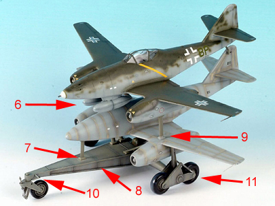
| Point:
6.
External fueltanks were not necessary, because the lower Me 262 held
enough
fuel and additional weight couldn't be managed.
7.
The front strut is a fall-over strut too and for that reason round.
Also
the hinges are much to massive.
8.
The trolley is made from welded steel plates! It has a boxlike shape
and
no bolts at all! For the steps on the sidewalls there are no evidence
at
all, but they make sense, because the vertical plate can be welded on
from
both sides.
9.
The hinges are to massive too. That the struts are fall-overs and round
shaped was told before.
10.
This support is a step, which only makes sense at the Ar 234 trolley.
To
get into the Ar 234 when it sits on the trolley the pilot used this
step
to reach the steps on the fuselage side of the aircraft..
11.
The wheels are standard tires, what can't be said of the ones used in
this
kit. The rims are fictitious and for nothing too.
|
to
6. The mounting points for the fueltanks have only been on the Bomber
version
of the Me 262. The U2 Version had had a different nose section
and
was nose-heavy too.
to
7. The struts on most of the Mistels were round tubes, only the JU 88
Mistel
main support struts under the fuselage have been streamlined tubes.
This
was used to cover the wires and lower the drag. In most cases the
special
tubing simply wasn't available and round tubes were used.
to
8. The shape of the trolley mainframe is fictious in all descriptions,
because no photos or plans exsist. The picture above even shows a plain
mainframe. I questioned the structural forces to the trolley while
designing
it and came to the conclusion that the I-shape
is the only one that makes sense. By shifting the sidewalls to the
center,
they can be welded on on both sides and reduce the load to the width of
the frame. Surely it were steel plates welded together not bolted!
to
9. The fall-over hinges consist of a triangular plate, bolted to the
wing
and holding a forkhead end of the strut with a bolt. Crude mounts like
here are not only wrong, they also look stupid.
to
10. This step on the front of the trolley doesn't belong there.,
because it makes no sense. The pilots only got into the cockpit by use
of a ladder.
|
|
|