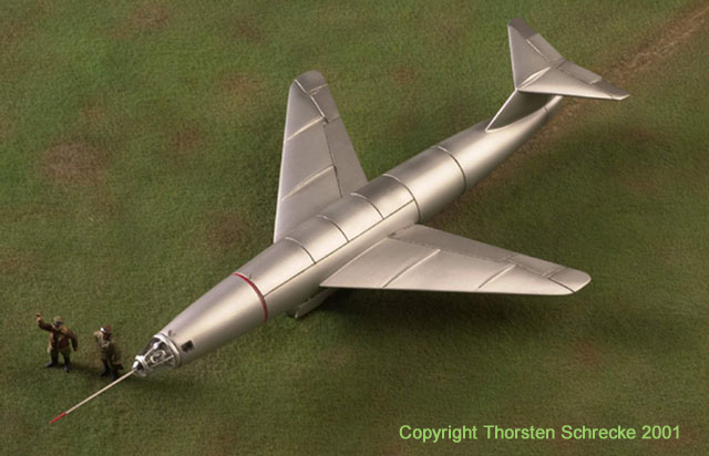
48 Special
Models owner
Thorsten Schrecke has a 30 years expierence as a modelmaker and is in
first
a film effects specialist. As a modelmaker the studied
animationdirector
has worked on a lot of movie projects, such as Independence Day. His
privat
interests are also the aircrafts of WWII and especially the exotic
ones.
So what is more natural than opening his own modelkitlabel, for all who
share his passion.
The
DFS-346 was one of his privat favorits and that is why it became the
first
kit of the newly formed label.
History of
Development
The
DFS-346 was a middle winged full metal construction and was under
developement at the end of the war in the Siebel Werke in Halle at the
Saale (Saxony). The plane was designed for high speed sonic and
supersonic
and high altitude testflights. Due to problems faced by German
engineers
while designing the new jet airplanes, the construction of a scientific
airframe was decided.
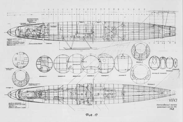
Original
drawing of the russian V1/V3 Version with sharp angled elevator (not
used).
Picture
via Helmut Walther
The
end of war prevented the finishing and testing of the DFS-346
called
testplane. The red army captured the plane and sent it to the USSR. The
in development involved engineers got the offer to continue their work
in the USSR. Facing the alternatives the engineers took the offer.
Almost
like in the "Operation Paperclip", when German rocket scientists around
Werner von Braun moved to the USA, it happended to the DFS-346
aircraftspecialists.
They were moved, with families and households to a small village
called Podbersje near by Dubna. Here two construction offices
(OKB-1
& OKB-2) were established. OKB –1 was headed by Brunolf Baade
and OKB-2 by Hans Rössing. Although the accommodation
had nothing to do with a prison or one of the feared camps, the Germans
were watched carefully. There was no doubt that the Russians only
wanted
their knowledge and didn't let them get new scientiffic results. This
proofs
the fact of P.N. Obrudow and A.J. Beresnjak beeing established as
deputizing heads of the construction offices.
At
the beginning of the work in 1946 the DFS-346 produced in Germany was
checked
out careful at the ZAGI-windtunnel T-101. From its shape was built a
more
advanced, longer version of the DFS-346. It was still called 346.
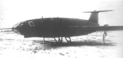
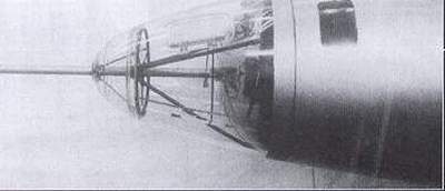
The
front fuselage of the 346 is a rotationbody based on the NACA-Prifile
0,0121-0,66-50.
The middle part was cylindric and narrowed to the square diametre of
the
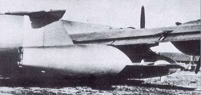
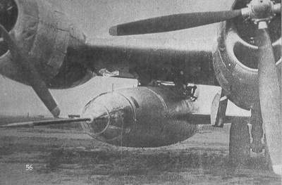
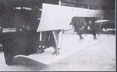
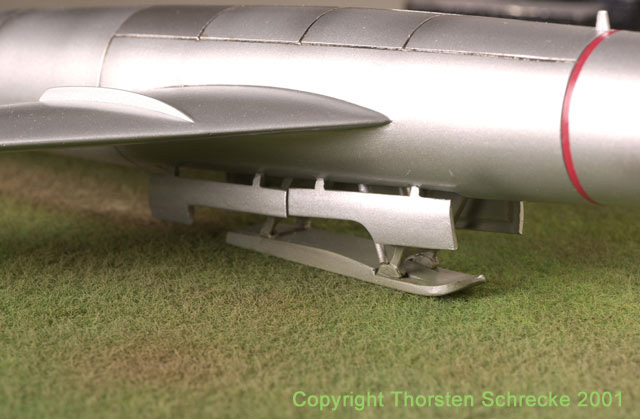
back. Presumingly for capacity and weight reasons the DFS-346 was
equipped
already in Germany with one of the loved landing skids. It was kept
later
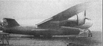
on too and caused trouble several times. The wings were 45°
swept-back
and got 25% average depth and a NACA- 0,012-0,55-1,25 profile with 12%
relative thickness. The area measured 19,87m2.
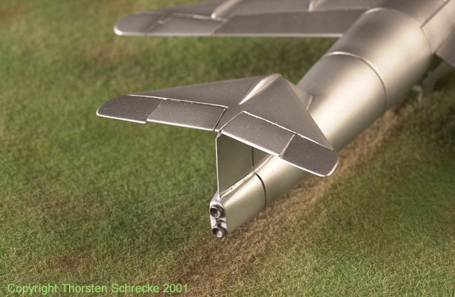
The completely continueing profile shape caused a stall in
certain
flight positions, which caused complete loss of control. This was
stopped
by use of fences on the top of the wings.
It
was motorized with a German built two chaimber liquid rocket engine
Walter
HWK 109-509, which was renamed ShRD 109-510 in the USSR. It had
36.7
kN of thrust on the ground and 39.2 kN of thrust in operational hight.
The DFS-346 could carry 1900 kg of fuel. It consited of hydrazinhydrant
with methlyalcohol and water. The oxidizer was 82% Hydrogenperoxyd.
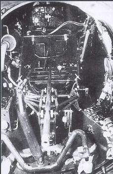
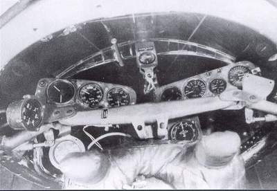
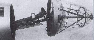
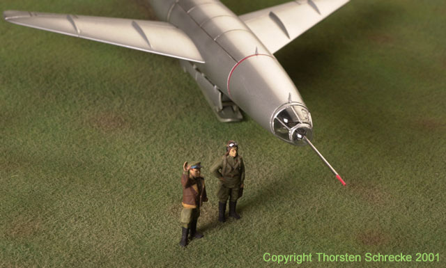
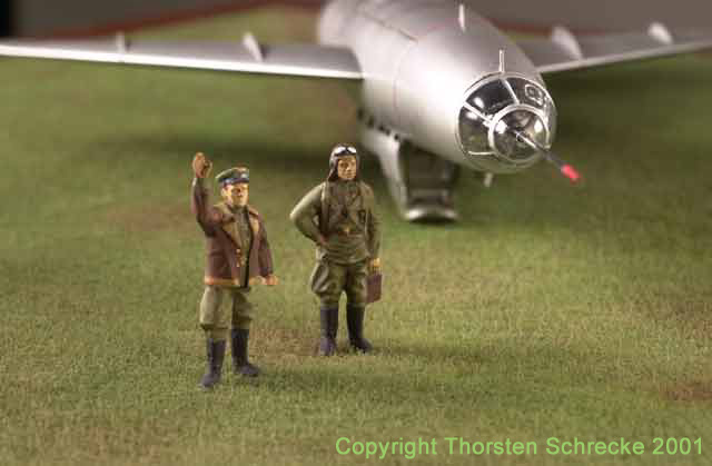
The
pilot was lying on a plank bed in a pressureized cabine, which also
worked
as an emergency system. This kind of position was very uncomftable for
the pilot and in certain flight situations almost dangerous. It was
chosen
for aerodynamic reasons.
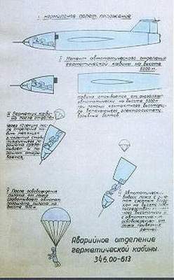
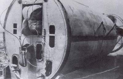
The
emergency system was very progressiv and worked, in opposit to the X-2,
perfect. The cabine was seperated from the fuselage by four explosive
bolts.
A dragchute placed in the backwall of the cabine stabilized the
cockpit.
In an safe altitude the plank bed including the glass dome was
catapulted
off the cabine. Another chute stabilized the flight and drew the pilot
off the plank. Then the pilots parachute opened and returned him safely
to the ground.
This
operation worked automaticly and was tested several times successfully.
Therefore a cockpitsection was lifted on altitude by a B-25J and
dropped.
The system saved the live of German testpilot Wolfgang Ziese on
14.
September 1951, when the aircraft went off control in 7000 m on a
rocketed
flight.
The
DFS-346 was built in several versions. The DFS-346-1 and DFS-346-3
where
used for flighttests.The DFS-346-P was a gliderversion without engines.
What happend to the surely built DFS-346-2 is unknown. The aircraft
differ
very little in design. Only elevator and rudder showed differences in
construction.
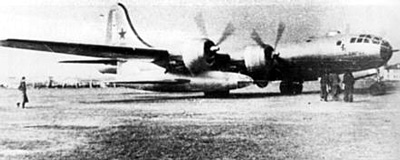
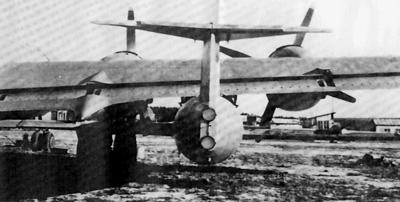
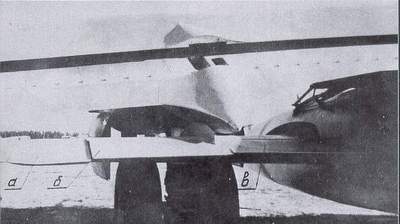
All
aircraft where lifted to altitude by a carrier aircraft and droped.
Therefore
an original B-29 , which had had an emergency landing in the pacific
territory
was used. Some say there were also a JU-388 and a TU-4 in use. But
there
are no photographs of it.