
R2-D2
Conversion
Autor
Th. Schrecke 2015
All Model Pictures Copyright © Thorsten Schrecke 2015
|
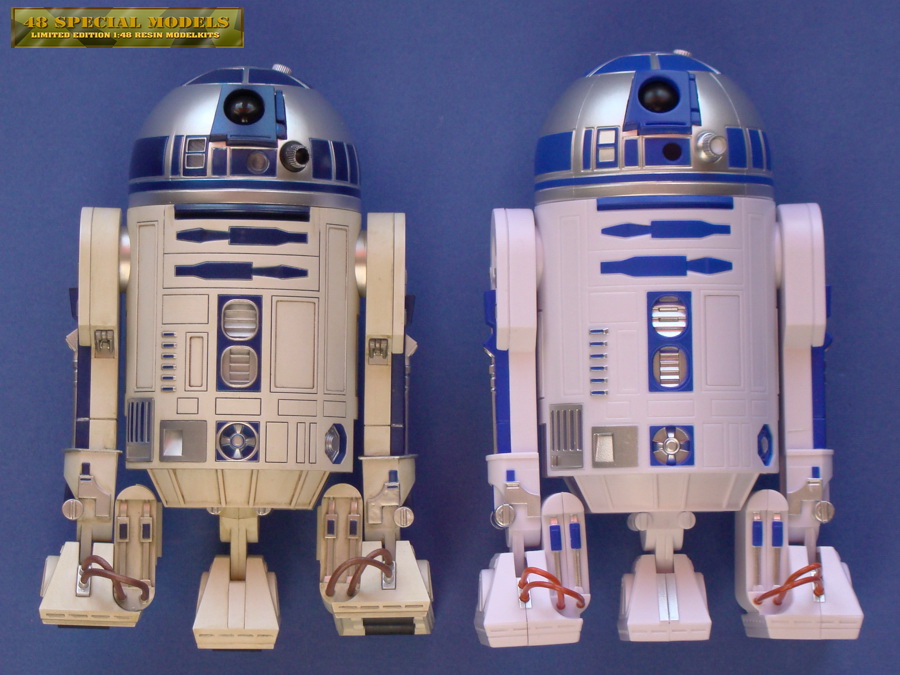
See here side by side the collectible which is quite expensive in comparison with the Money Bank/ Alarm Clock version.
Bothe models are photographed side by side to show the size.
The left one is the collectible.
Note the rolls at the collectibles feet and the thick soles of the cheap copy!
|
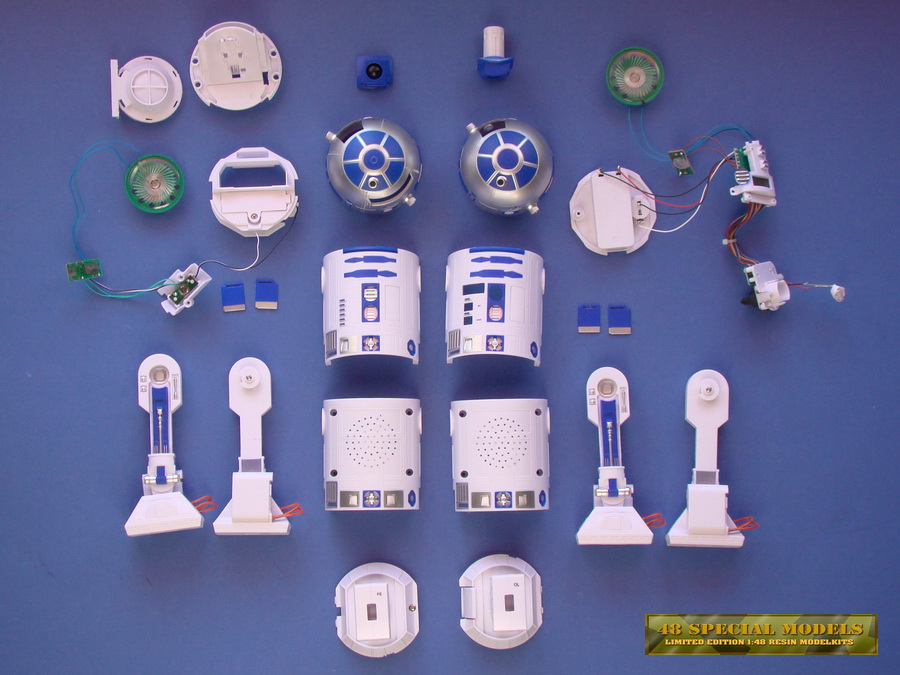 |
Taken apart and presented as a parts kit. The left side half is the money bank and on the right is the alarm clock.
It is obvious that both items where made from the same basic design model and varry only in the functional parts!
|
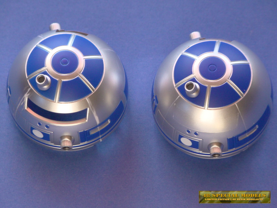 |
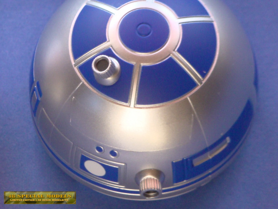
Most visible it is on the
head pieces. Here the same mold was used for production. Only the slot
was blocked off on the alarm clock part by an insert part in the mold.
Unfortunatly not very well done, becuase it is clear visible and needs
some sanding and other treatments.
|
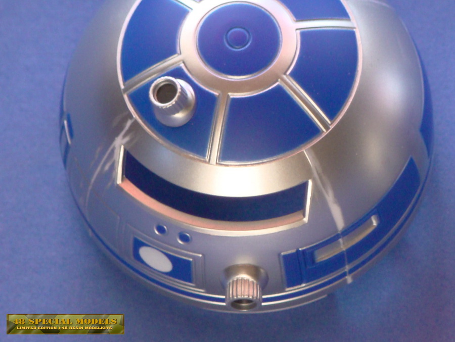 |
The sphere also has structures that nned to be removed and smoothend. On both items!.
On the money bank the slot needs to be closed and fillde and sanded too.
The outstanding projection optics are only stuck in and welded on the
back. They can be removed by routing the weld seamcareful. This makes
sanding an spraypainting much easier.
Also they may be drilled open for putting in LED-lights too.
|
 |
| On the alarm clock sanding and painting only will do. |
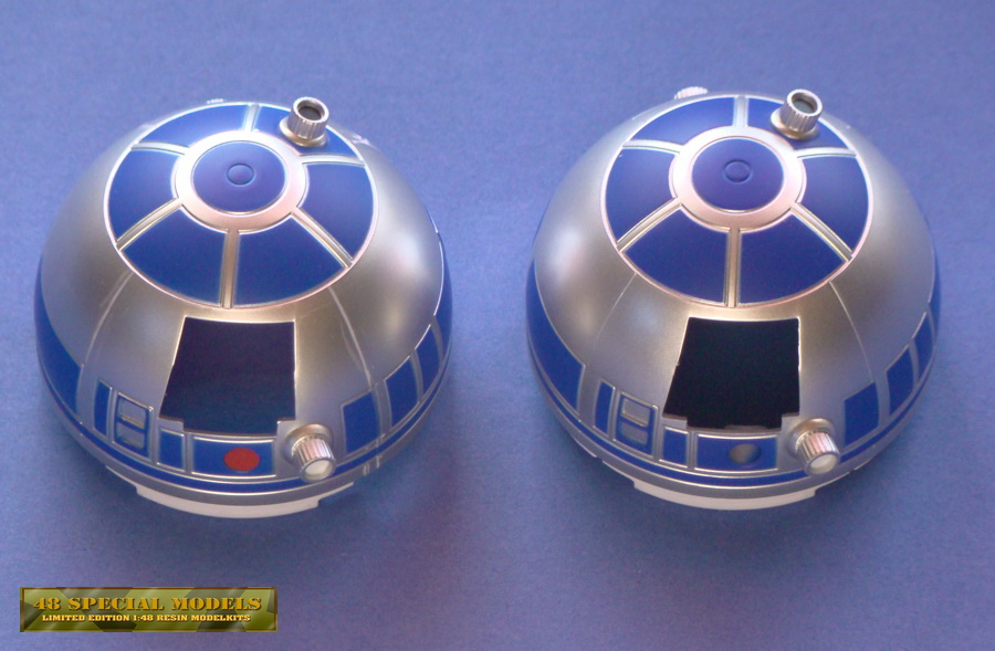 |
| Left is the money bank, right
the clock. the clock has a red dot instead of the hole for a LED light.
This is helpful, because on the money bank it has to be drilled first.
The blue block with the black lense can be removed easy and is
interchangeable. |
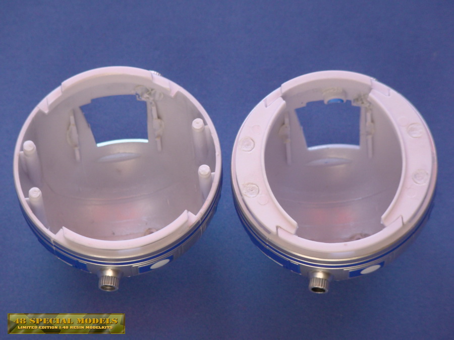 |
Left is the money bank again. Notice the missing supportring parts and the LED-attaching hole on the upper rim.
|
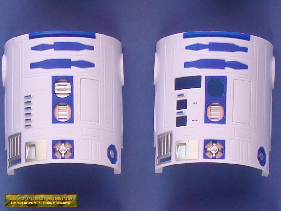 |
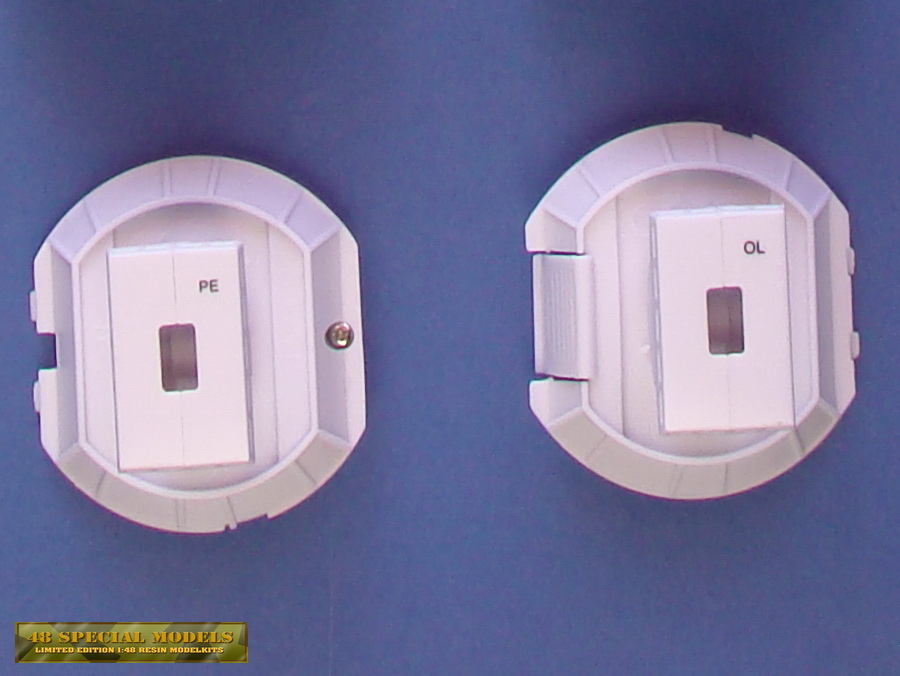
Most visible are the
differences on the front surface. On the left again the money bank. The
clock has a LCD-display left side up and two push buttons below of it.
The upper cut out in the middle is just for placing the
electronics unit part into place correctly. On this part all the
switches and displays are connected. Right beside this on bothe items
you will find the DEMO button, which in in place here.
|
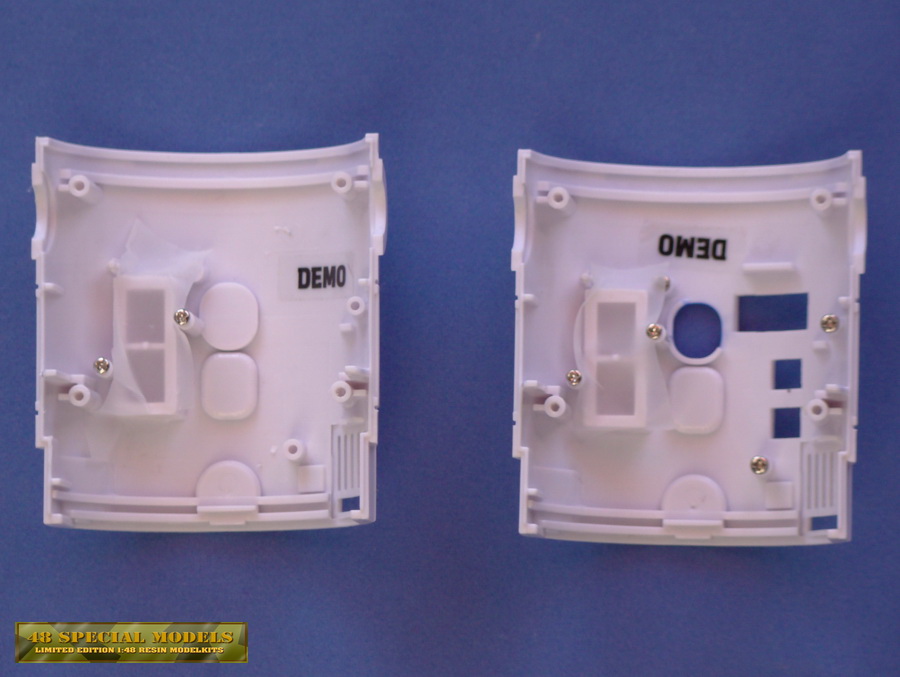 |
The back of the frontpart
shows off the secrets of electronics installed. On the left side is the
money bank again. The DEMO button is fixed with a piece of tape, to
prevent it falling out while the switch is taken out. On the lower
right side the plate behind the ventilation grid was taken out too.
|
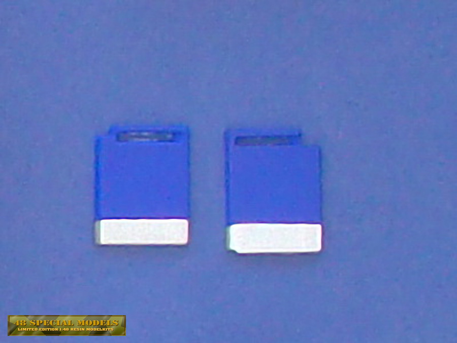 |
These are the plates from behind the ventilation grid. They are the same in both models.
They are just welded to the plastic and can be removed easy and without being damaged.
|
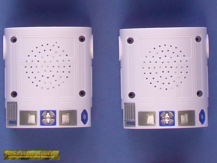 |
The backs are identical on both items. The holes are for the speaker and need to be closed.
The four larger holes are the main screw holes that take the screws for holding everything together
For what reason ever the lower left one was hard to open on both of the items.
I managed it to open them by use of a slot screw driver in a fitting
size. I had to use some pressure and force, but after a while it turned!
But they are all Phillips screws!
Still after getting the screw removed I couldn't find out why it was blocking. Probably the glued it in as a security.
|
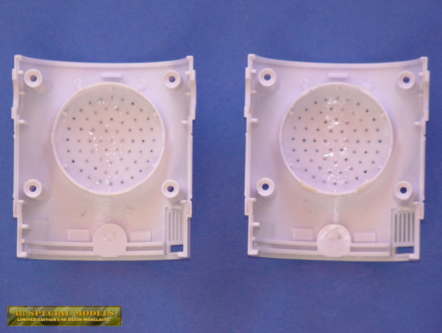 |
On the Money bank the speaker is covered with a plastic part to protect him from the coins.
In the clock this part is missing. Thats the only difference between both parts!
I covered the holes from the outside with some tape and filled them up wit superglue from the inside.
Use a mid or thick superglue, because it fills up gaps.
|
 |
Besides the heads the bottom
parts are the most differnt in making. Depending on how much you care
for detail this means more or less work. The middle leg can be removed
easy be unscrewing it from the inside.
|
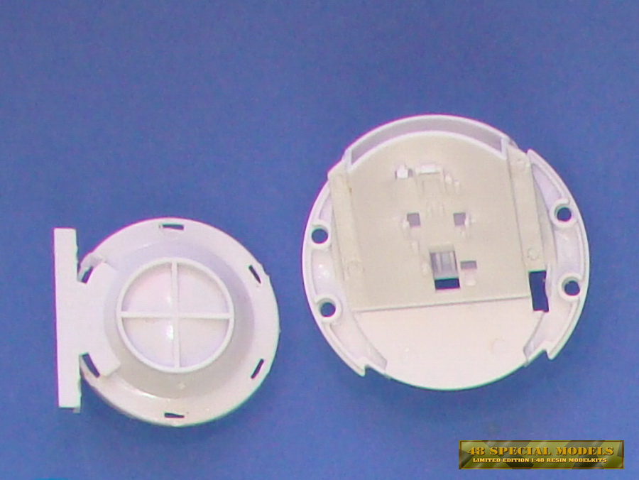 |
The left part is the speaker cover, right is te coins slot construction with support ring.
The speaker cover may be used later when the
new place for the speaker is found. The coins slot construction can be
deposed off except for the support ring, which is usefull, but not
important for function.
|
 |
The main legs don't have rolls on the lower side of the feet, but a rectangular hole!
The parts are cemented together and can't be taken appart without
force. This makes converting them and filling up the open space in the
legs strut with a cover, a bit more complicated. It can be filled up
with epoxi putty in layers or by use of a polystyrene sheet which is
cemented in place. The joint plates on the top of the leg can be taken
of by unscrewing them. They limit the legs way by help of the sector
cut out of the disc, which makes sense.
On the collectible the boxes on the inside of the feet have a cover
sheet and a round structur applied on, which are missing here.
These can be made of some 0,5mm thick plystyrene sheets cut to fit and a 2mm rod. See photos on the original for reference. |
|
Yes, these are 1/6 scale!
So if you want to modify a R2- Robot in any other color or type or if you want to save some money or get the time projected, these are the R2-Units of your choice! And you get some extras the collectible even has not!
The alarm clock will get you out of bed any time you want to and shows
you the time projected to the wall. Well it doesn't look like Leia, but
it works!
The alarm clock has a turning head section like the real collectible too,
but a different, but working lense. It comes with light and soundeffects
as well and is about 2mm higher than the collectible. The paintjob is
not as perfect as on the handpainted collectible, but that's for the
birds! When you see the price you are willing to take up the brush
and do the painting yourself, trust me!
Main difference is the back of our favorite droid. It looks like he has
had a shotgunn attack from short distance with big bullits. As long as
you show him from the front it doesn't matter at all, in other case
some modifictions are needed.
The Money Bank version has a slot for inserting a coin in the back of the head,
which also can't be turned around too for that reason. But it has a
front section without cut outs for the clock and a dark main lens. The
rest of the robot looks the same, including the holes in the back and
the missing covers on the inside of the legs.
Ok, there is two ways to get happy with this model instead of the tripple as expensive collectible.
First you don't mind the differences in the look due to the benefits of alarm clock or money bank.
Second you get both models and start your modification tour with beginnig to dissassemble them.
But first go non reading this article!
If you have the collectible already, you may just use this for a guide
for modifications. If you don't mind a static head section you even get
away cheaper, because you just need one model. Same is if you cover up
the clock with a part of plastic sheet and find a button that fits the
black main lense!
The missing covers on the inside of the legs can also be added by
putting in some plastic sheets or filling them up layer by layer with an epoxy putty. And the rest will be sanding some
edges, spraypainting and brushing the whole unit until it has the
wanted look!
The absolute nerds may cut off the soles of the robots feet and add
some rolls for making it roll around like the collectible! But to be
honest, who rolls him around at all?
If you want to get rid of the holes in the back, you have to accept
that the sound will not be the same after covering them up!
The
collectible version I have got the speaker mounted in the head and has
some slots on the top of the head. This looks even worse in bright
light, but isn't visable in low light mostly. So we end up with real
movie mockups, one for each possible lighting situation? Well, I guess
its everymones own decission!
To cover up the holes a simple way would be dissassembling the body
halfs by unscrewing the four screws on the back. For what ever reason
the below left screw is hard to move and needs a slot screwdriver to be
turned, although it is a Phillips screw?! Probably it was glued in for
securing it.
Take the part of and
remove any electronics parts carefully without breaking them. It helps
to make d photo of the installation, if you need to remember it!
Disassamble the whole unit first as far as possible.
Use some duck tape and cover up the holes carefully from the outside!
The more accurate you do this, the less work with sanding and priming
will follow on!
Get a putty that sticks to Polystyrene, such as polyurethane putty or
model putty. Fill some of it in a syringe and apply it to the holes.
You may also use superglue and a filling component like talkum powder
to fill up the holes. Thats's what I did. Let it set until next day to be sure it will not
leak out when taking of the tape!
Next day you will see what happend. If the tape was applied thight
enough, only the holes will be filled and nothing was leaking out. This
will help you getting a perfect surface. Sand it with a fine grain and
spraypaint with white primer very thin.
Still the scew holes are a problem by now, but there is help. You have
to decide if you want to open up the robot ever after. If you want
to, use
a white plastic rod and cut it to fit inside as fare as possible. Take
a pencile and mark the holes edge. Take out the rod and cut and sand
him to fit. When assembling again finally place them into the screw holes.
Another way would be filling up the hole with some paper from a
papper towl. Stuff it in careful and 2-3mm below the end of the tube.
Add some putty on top of that and leave a little bulge with an
overspill, only in the hole! Apply a piece of tape to the hole
and press it even with a spatula or similar tool to structure it like
the surface. Let it set and after that remove the tape and sand to fit.
This way you get a small cap, which in case you need to open the robot
again, can be drilled through easily! The papper is just for preventing
the putty to be presse deeper inside as intended.
You may use both models to set up one new complet unit form the best
parts of both of them, or use both and some mor work to make two units
of different look!
In the last case you need to cover up the coin slot in the back of the
head. Before this happens you should take off the projection lenses
that peek from the head and are welded from the inside to keep them in
place. Luckily this helps to remove them without further damage. Just
use a mini drill and a router bit to cut away the molten plastic around
them until they drop out.
Store them in a secure place so they don't get lost!
Now the head of the R2-unit is smooth and bumps free sand off the
grades and put a piece of tape against the inside wall of the head.
Cut a thin cardboard in the negativ shape curved like the head,
which fits the quarter of the sphere. drill a 1mm hole right in the
middle of the top of head and make sure its centered! Glue a pin to the
cardboard, so you can put it into the hole in the head and turn around
the pattern along the heads surface without gaps. Now apply a thin
layer of a smooth modellers or epoxy putty to the gap and shape it by
use of the pattern. Do in steps and let set completely after each step
if necessary. This way the slot will vanish and have the correct shape
too. It also reduces sanding afterwards. Cover the drill hole
afterwards too and sand wet with a fine grain untill the surface is
adjusted.
If you want to upgrade yourunit with some extra lights its the right to
do this now. Cut out the holes and gaps needed in the head
sphere. Drill holes to the projetcion objectives that you had removed
beforehand. Use a handdrill and coolingagent when drilling, becaus they
will get thin walls. Its also clever to drill in steps, starting with a
small diameter, getting larger each step.Final size will be the
diameter of the LED you want to put in.
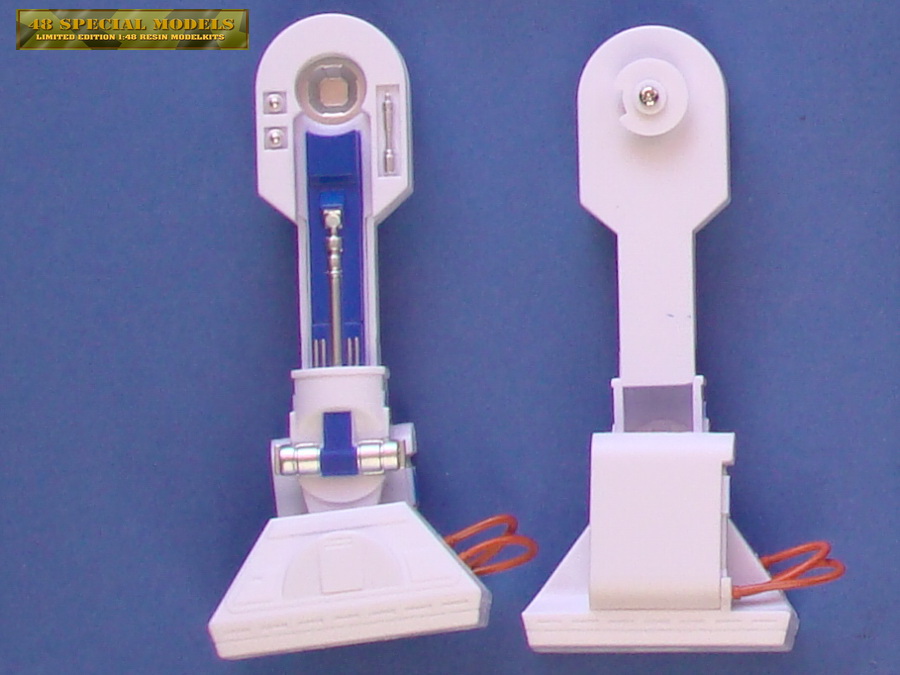
The head can be turned in the Clock version, but not in the money bank
version! Well that's only half the truth. It can turn, but you have to
remove the coin slot for that first! So the feature will not be
available at the end at all, it doesn't matter to remove this part
completely. The part is welde on again, which makes it easy th get it
out without damaging it. Just cut of the welding seam. In general the
part will get off withot problems or damage.
As to be see in the parts picture above, the coin slot is connected ot the
support ring, which make the half ot the guiding ring for the head. It
si not realy needed to make the head turn, but to let it run smooth I
recommend to cut this part of the coin slot and weld or glue it back in
place. Do this after having all the LEDs mounted and connected, because
the parts limit the space inside the head for working. Finally it
should look like the right head on the pictur above.
The Front Section
The both front sections are different in some ways. Therfore they need
to be treated different as well. The money bank almost needs no
modification, besides taking out the blue plates from behind the ventilation grid, to make painting easier later on.
The clock has some more parts connected to the front part, such as
the clock's electronics assembly, which has some switches that go
through the front. THese have to come back in place later after
painting. The DEMO-button is available on both items and should be
after conversion, for starting the sound and other functions. I
kept the screws on the inside in their holes so they don't get lost,
because these are needed later for assembly.
So these parts are ready for painting after that!
The Back Section
Inside the back the speaker is installed in both models, but only the
money bank has it coverd with a plastic part for protection. They are
both welded in the known way and can be removed as discribed before.
You should keep the speaker connected to the electronics, this way you
don't have to solder it on later again.
From the ouside the holes in the back need to be coverd wit tape. I
used a scothc transperent office tape which you can see though and
which seals the surface around the holes tight. From the inside I
applied superglue to the holes and let it set. This may be done
severals times for bubbles will occure and open up while setting, so
the holes will need another treatment.
Let it set about a day or too to make sure is hardened trough
completely, then take off the tape. This might be not as easy as
expected, due to the superglue. So use a xacto knife to lift the tape
and cut it from the holes. After that the abck mad be sanded and primed
first and then sanded again as long as needed to make an even surface.
The Bottom Section
These parts look different, because of their function. In both models a
battery compartment is installed, but with different batteries. Belo
that the Cover with the middle foot is attached. The Foot is screwed on
from the inside only, so it can be removed for further treatment and to
get space for working on the bottom part.
Because you will need to get access to the batteries compartments on
both units the posibillities of conversion are limited.
Fortunately this areal of the model is to be seen very limited
and for that you may leave it as it is. But if you want accurate
details you have to modify it true to the original.
On the clock version this is easy. Only the screw gap needs to be
covered up with putty or a plastic part. To keep the screw working will
be a bit of a problem here.
On the Money bank there is a bit more to do. First the opening
mechanisem need to be cut off. From the inside the gap will be closed
with a plate of polystyrene on which a second plate will be fit in
thightly to cover up the surface as well. Same will be done wit the
gaps where the battery protection strips were located. Well, the real
nerds may install the shaft for lifting the middle foot by doing it
from scratch and also making the foot turn around too!
The Legs
The legs nee not much to be converted. Most obvious is the gap on the
inside of the legs. This can be coverd up with another plate of polystyrene or by filling it up with epoxy putty in layers and sand it to fit.
So the feet can't be removed without using brute force, due too the
fact they are glued and pressed together you should think about
conversions here careful.
It might be possible they will be damage doing this.
In case you want to, a good idea would be starting sanding off the
soles, because they are to thick at all. Measure the thickness until to
the first goove and take off half of it. This way you will get a look
inside them too. To add rolls to the feet cut a fittin plate and mount
the rolles by scratchbuilding them to this plate and glue it to the
foot again. Cut and sand the Edge to fit afterwards, done. Add some
missing Details to the legs outside, by looking at the original first
and scratch buildingt the missing parts then.
The leg has a disc like part in the joint with a cut out section,
which limits the way it can be moved. The collectible doesn't have such
a limitation. The legs can be turned 360 degrees around! Nontheless
this limitation makes send for a stable stand of the figure. Therefore
I wouldn't change it at all.
Perfectionists now can do their thing and finish the R2-Unit the way
they want it to. They may even give it another of the many astromech
droid colors that run around in the Star Wars Universe!
This is the cheap way of building an astro mech army!
To be continued...
|
|